
Building a legged robot in 80 days: Lessons learned, tears shed, blood spilled.
This is the heroic tale of how a team of five dedicated individuals designed, assembled and programmed a six-legged hexapod robot within 80 days starting from scratch. The article takes the format of dated diary entries. Since the work was completed while keeping up with family, work and community obligations the diary does not show a neat linear progress from start to finish – real life is rarely so simple. Instead there are large leaps forward followed by weeks of little to no progress. This article attempts to reflect reality and not to be some fairy tale with a convenient story arch. However, if you, dear reader, accept those preconditions then there are many gems to be found.
Introduction
The European Land Robot Trial (ELROB) is an annual event with a focus on providing a real-world testing ground for various robotic systems. The tasks required of the participants roughly stay the same although the competition alternates between civilian applications such as search and rescue and military applications such as reconnaissance. The competition is hosted by a different country each year.
In 2020 a ELROB with a focus on military applications was supposed to be hosted by Austria. Unfortunately the event had to be postponed to 2021 due to the outbreak of the Corona virus. In 2022 the competition was once again cancelled due to the Corona virus and was rescheduled to 2023. Due to the repeated pattern of an hopeful announcement followed by a crushing cancellation I lost sight of participating at ELROB while working on more pressing concerns. At the begin of March 2022 I once again took a look at the ELROB homepage and discovered that this year ELROB was actually going to take place. Alas, the deadline for application had already passed and there were only 87 days left to the official start of the competition, for which I had no robot.
I took a couple of days mulling the situation over but ultimately the desire to have a go at the competition won out over concerns of an extremely tight deadline. The first order of business was to assemble a team. Thankfully I could recruit Bernhard Mayer, Jonas Wühr and Pavel Kirienko to the effort. Robert Hahn, OE3BHC, a ham radio friend of mine later joined the fray to precision-manufacture the many shafts required for the robot.
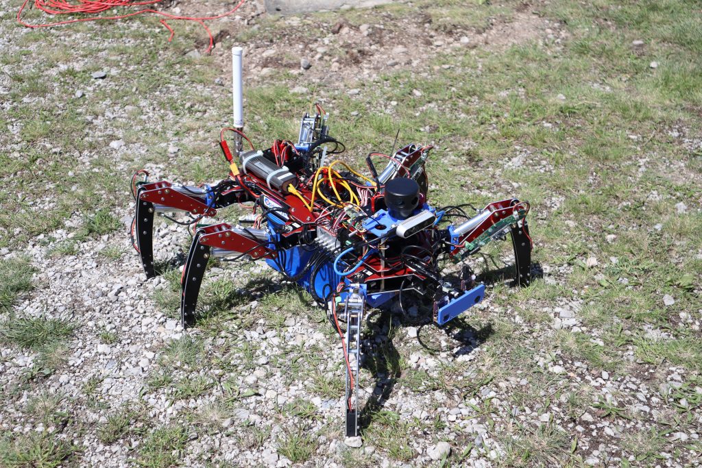
I’ve always been fond of legged robots, since they have an edge over wheeled or even tracked vehicles when traversing rough terrain. UAV’s don’t need to bother with the underlying terrain at all, however there are severe energy constraints on how long they can operate. Loitering or simply staying on a spot and observing with little to no energy consumption is next to impossible for flying robot. Adding a long-time fascination with six-legged hexapod robots to the mix it became rapidly clear what kind of robot I intended to build. The project was christened L3X-Z which is a phonetic wordplay on „legs“ as well containing the company names LXRobotics and Zubax Robotics.
T – 114 days: Work space simulation and linkage design for a potential legged robot
Although I had not even found out yet about ELROB taking place this year I had been constantly playing with various concepts for building a hexapod robot. And while there is a considerable number of hexapod robots with fully electric joints those are unfortunately limited in terms of joint durability and maximum robot weight. I wanted to go a different route and build a large-scale hexapod capable of carrying a considerable payload. In order to generate the required power to lift the robot’s legs I decided to power the force-intensive femur („thigh“) and tibia („lower leg“) with miniature hydraulic cylinders instead of electric servo motors.
A primary concern when designing a legged robot (or any manipulator) is the achievable work space. A large workspace enables you to step over obstacles and crouch below overhangs. A tiny work space means that you can perform only very small steps, even when you have very long limbs. When you are working only with pen and paper this task can become daunting very quickly. Thankfully I found a free software tool called Linkage Mechanism Designer and Simulator which I used to prototype various different lengths for femur and tibia, different kinds of cylinders (varying in their length when fully retracted or extended) and different positions of the rotational axis and cylinder mounting.

T – 87 days: ELROB 2022 – to go or not to go?
After finding out that ELROB would in fact take place this year and despite a strong initial desire to participate in the event the actual decision to go was not made lightly. The deadline for registration had already passed, I had no robot and the event was less than 90 days away. After thinking hard about the situation for a couple of days I came to the conclusion that it could be done but only with the help of an experienced team. Before officially trying to obtain a place on the competitions roster I first went out to recruit a team: Bernhard Mayer and I have a decade-old relationship of jointly working on robotic projects. Jonas Wühr was brought in by Bernhard Mayer, as they are members of the same robotics club in Bavaria. Pavel Kirienko – whom I happened to know via our collaboration on the OpenCyphal project – was swayed to come to Austria by promising delicious Austrian cuisine.
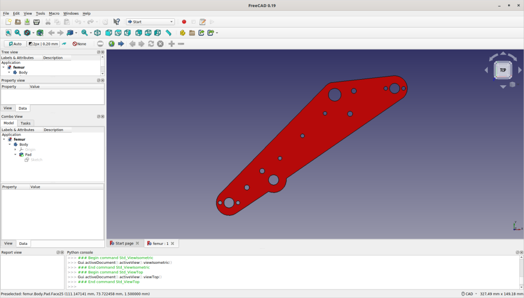
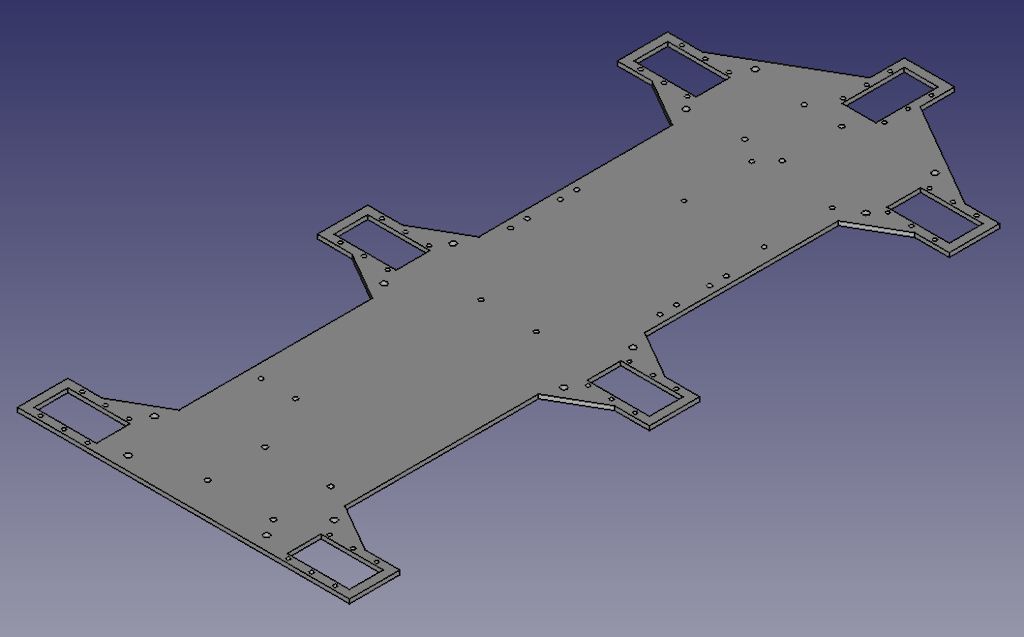
T – 85 days: Designing a hexapod leg with FreeCAD
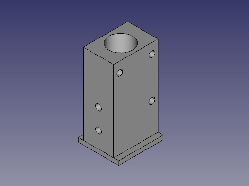
In parallel with assembling the team I designed the first version of a hexapod leg using FreeCAD. The tool was chosen for multiple reasons, the most important of which are: personal familiarity with the tool, cost (or lack thereof) and the ability to export parts as DXF files (it’s not straight forward but it can be done). All custom milled plates in the final robot have been manufactured by Schaeffer AG. The company is specialized on creating customized front plates but its tools and processes can be diverted to mill any custom parts up to a height of 10 mm.
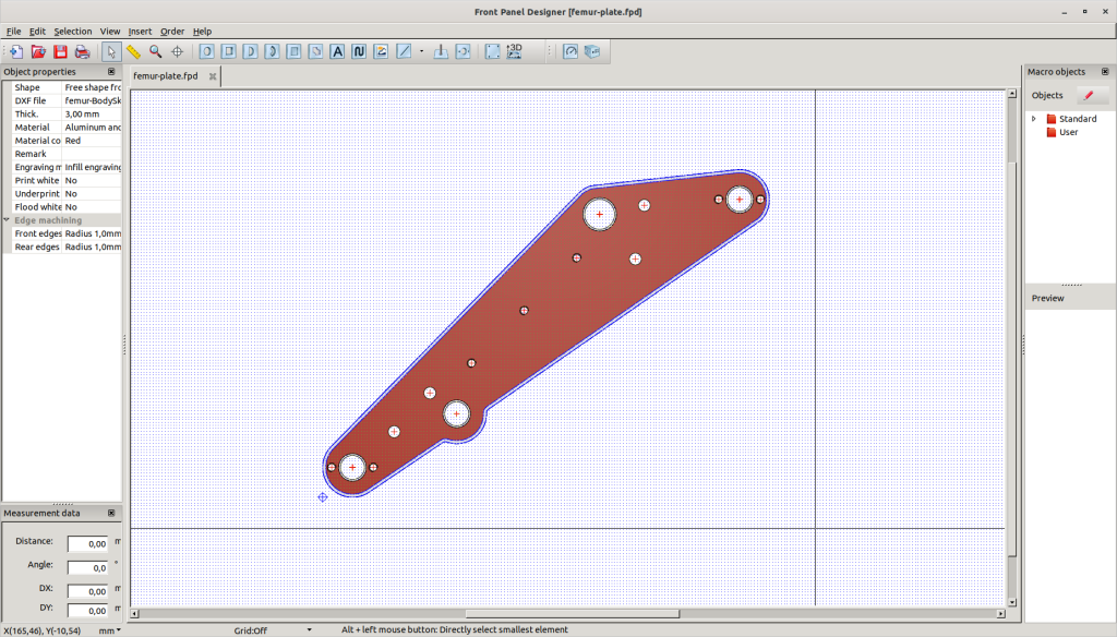
Schaffer is providing a multi-platform tool called Front Panel Designer which allows direct import of DXF files to define the outer contour of your front panel (or hexapod robot leg). The holes or cut-outs can also be exported as a DXF file from FreeCAD and re-imported into Front Panel Designer. A word auf caution: One has to be very careful in aligning the contour DXF file with the hole DXF file as otherwise the holes in the manufactured part are not where you’d expect them to be.
T – 80 days: Official application for participation at ELROB 2022
After successfully recruiting the team and confirming everyone’s availability I filled and sent a ton of paperwork (i.e. the events application forms) to ELROB’s organizing body, the Fraunhofer Institute for Communication, Information Processing and Ergonomics (FKIE). Despite considerably overshooting the official registration deadline initial feedback was positive so we decided to go ahead full steam breathing life into a robot that so far only existed in our imagination.
T – 74 days: Assembly of the first leg prototype
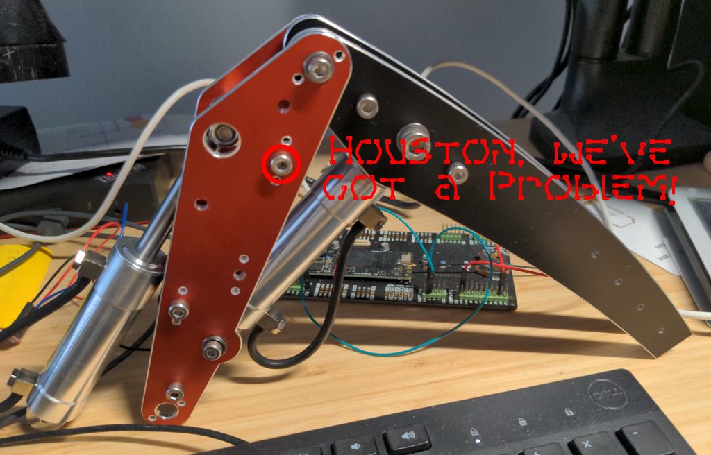
After arrival of the custom milled plates I immediately assembled the first leg prototype using screws as substitute for the as of yet not available shafts. Upon completion it rapidly became clear that there’s a problem with the design: The tibia cylinder is blocked by one of the screws connecting both femur plates before it could reach full extension. In the worst case this could have led to leg damage should software control have failed to stop cylinder expansion before reaching the maximum allowed extension length. Not achieving the designed range of motion for the tibia joint also limits the work space of the leg. At any rate a design should be fail-safe to prevent physical damage even in case of software failure. Back to the drawing board …
T – 65 days: Assembly of the hydraulic valve blocks
While L3X-Z’s hip joints are actuated by Dynamixel MX-28AR servo motors femur („thigh“) and tibia („lower leg“) are powered using hydraulic cylinders as those limbs bear the brunt of the robot’s weight. As L3X-Z has six legs and each leg contains two hydraulic cylinders this means there is a sum total of 12 cylinders to be controlled. Cylinder control is done via suitable valves which can be used to control the cylinders state (expand, retract and hold) as well as the speed with which the cylinder extends or retracts.
Note: The speed of extension or retraction does not only depend on the valve but also on the flow rate provided by the hydraulic pump as well as how many cylinders on the same hydraulic circuit are actuated at the same time.
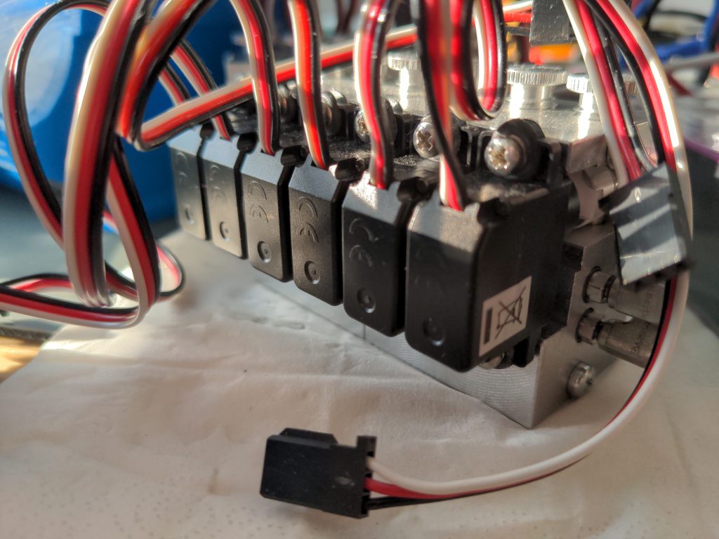
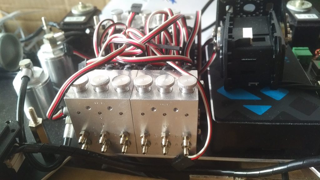
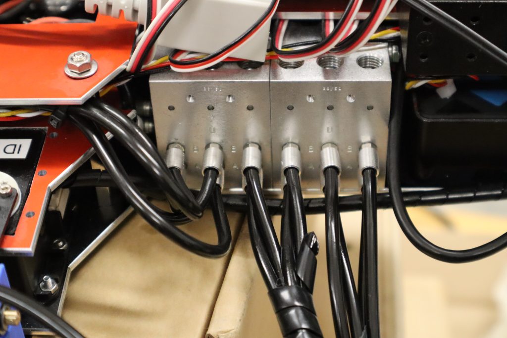
L3X-Z uses two Leimbach Modellbau 0H506 valve blocks – and two separate pressure circuits – each consisting of six independently servo-operated valves.
Each hydraulic valve is actuated by a FUTABA S3107 micro servo which in turn is controlled via the standard 50 Hz/1-2 ms PWM signal commonly used in RC model building. On the right side of each valve block the inlet for the pressure circuit as well as the return outlet leading to the hydraulic reservoir can be seen.
T – 63 days: Assembly of the second leg prototype
Seven days after detecting and rectifying the issues of the first leg prototype the parts for the second leg prototype arrived. There were still no custom made shafts available so M4 and M6 screws were used for its assembly.
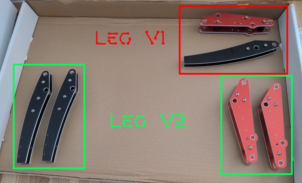
Writing this article I found only picture where you can see both the first and the second version of the leg. It’s not perfect for side-by-side comparison but if you look closely you’ll be able to spot some differences:
T – 61 days: Dynamixel MX-28AR hip joint installation
With only 61 days left to the official start of ELROB 2022 we had to move forward speedily. L3X-Z’s base plate was designed and sent off to manufacturing only a couple of days after the plates for the legs had arrived.
After arrival of the base plate the first order of business was to check if the servos really would fit into the openings designed for them. Thankfully this proved to be true so I went ahead by upgrading the firmware of all Dynamixel MX-28AR used for hip rotation to the 2.0 firmware using the Dynamixel Wizard 2.0 tool. Furthermore a unique id was set for each servo where each leg is assigned a number from 1 to 6 which corresponds to the hip servos network id.
A bit of background on the servo selection: The Robotis Dynamixel MX-28AR was chosen because of its high-resolution 12-bit absolute position encoder, a high stall torque of 2.5 Nm and its usage of RS485 (as opposed to the standard TTL interface) for communication. RS-485, as opposed to default TTL, is a differential bus and has therefore a higher resilience against common mode electromagnetic interference. This is a relevant design criteria in a tightly built robot where power lines are sometimes closely located to data lines.
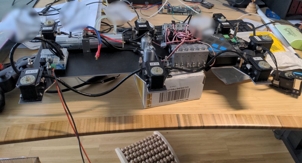
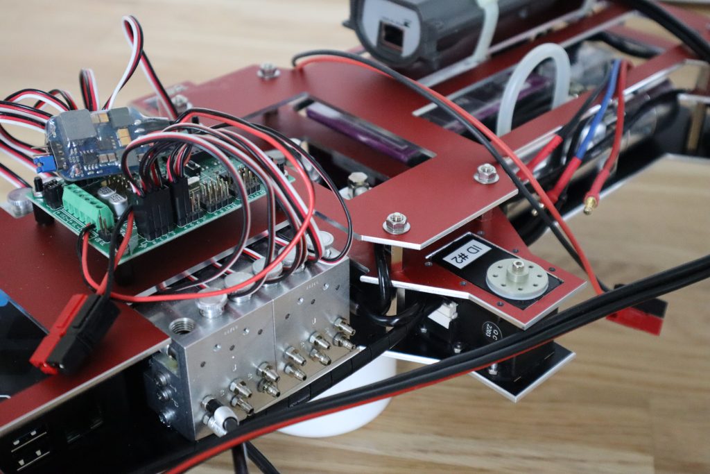
T – 60 days: Installation of hydraulic pump, valve blocks and oil filters as well as a Robotis USB to RS485 interface and a battery to USB-C power block
With the hip joint servos mounted it was time to turn my attention to the installation of the robot’s hydraulic components. I had not worked with hydraulics before so I was breaking new (to me) ground. A Leimbach 0H108 dual-pressure-circuit hydraulic pump was installed to the rear of the robot. This was followed by two Leimbach 0H130A hydraulic oil filters, visible as vertical cylinders in the center of the robot. Right of the center (and on both flanks of the robots) two Leimbach 0H506 valve blocks.
After completing the installation of the hydraulic components the next step was to interconnect them forming the required hydraulic circuit. For this Leimbach 0H058 – black silicon tubing with outer diameter Ø = 4 mm and an inner diameter Ø = 2.5 mm was used. The hydraulic circuit starts from the pumps pressure outlet P via the oil filter to the valve blocks pressure inlet P. The return circuit is running from the valve blocks tank outlet T directly to the pumps tank inlet T.
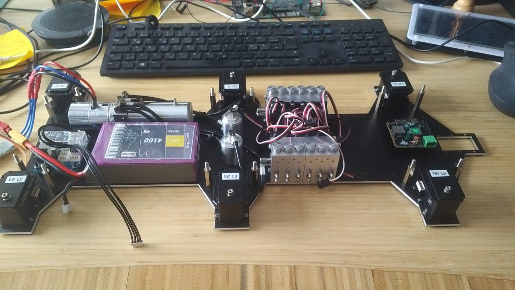
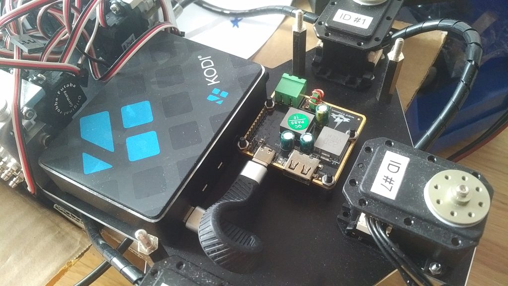
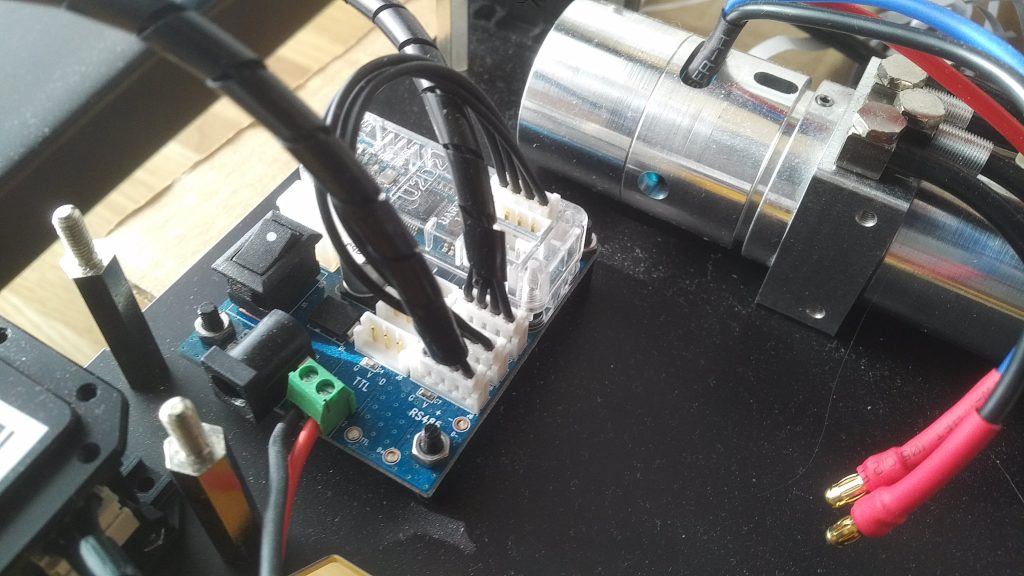
For a dimension check I placed the 4-cell 4100 mAh LiFePo rechargeable battery was placed at its intended position next to the hydraulic pump. Behind the battery a Robotis U2D2 USB-to-RS485 interface converter in combination with a Robotis U2D2 Power Hub was mounted. The purpose of this board is too a) provide a bridge between the main computer and the Dynamixel MX-28AR RS485 network and b) to supply those servos with sufficient power which is directly provided by the main battery. At the base plate’s front of a Cooltech WTF-CCG3PA_V3 board is mounted which allows a direct conversion of the main battery’s voltage to USB-C, required for powering the Raspberry Pi 4 main computer.
T – 59 days: Installation of L3X-Z’s Raspberry Pi 4 Single-Board Computer
A Raspberry Pi 4 Model B (w/ 8 GB RAM) single board computer (SBC) enclosed within a FLIRC Kodi case as protection against dust and dirt was installed in front of the two valve blocks. Furthermore the vendor provided electronic speed controller was connected to the brushless motor responsible for driving the hydraulic pump.
T – 55 days: First test of complete hydraulic circuit
Time to run a first test and see if the hydraulics actually work! As a test setup one leg’s tibia cylinder was temporarily connected to one valve:
Starting up the hydraulic pump it came to our attention that the vendor-provided electronic speed controller was in fact under-powered to drive the hydraulic pumps brushless motor, a fact which was promptly communicated to us by the rise of smoke signals.
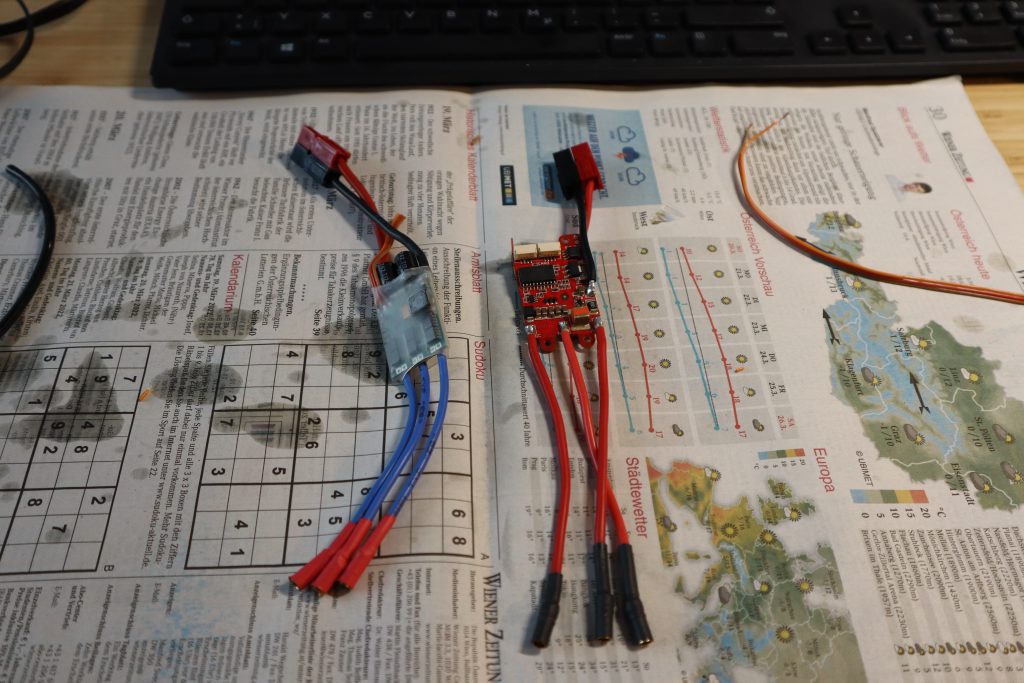
From a previous and unrelated project a couple of Zubax Robotics Orel 20 were available so the vendor provided ESC was swiftly replaced by one from Zubax. The Orel 20 has the added benefit that this electronic speed controller can be controlled via OpenCyphal/CAN (compared to default PWM of the other ESC) which allowed us to use one CAN network to control all the robots sensors and actuators (more on that later).
With the Orel 20 we were now able to successfully drive the hydraulic pump, allowing us to extend a retract the tibia cylinder of a single leg:
T – 45 days: Wiring the RS485 Dynamixel bus and mounting servo horns
The Dynamixel MX-28AR smart servos were linked together with a 4-wire cable that had power and ground, as well as the RS485 differential data lines (D+ and D-). Two more Dynamixel MX-28AR smart servos were added and linked to the RS485 network so that the L3X-Z camera head could be controlled by pan and tilt.
A very flexible USB-C cable was used to connect the Cooltech WTF-CCG3PA V3 LiFePo-to-USB-C converter to the Raspberry Pi 4.
The Robotis U2D2 Power Hub will be directly connected to the 4-cell main LiFePo battery to supply the power required for the servos to operate properly. A black/red cable terminating in an Anderson PowerPole connector was attached to the board to accomplish this.
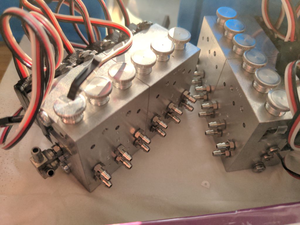
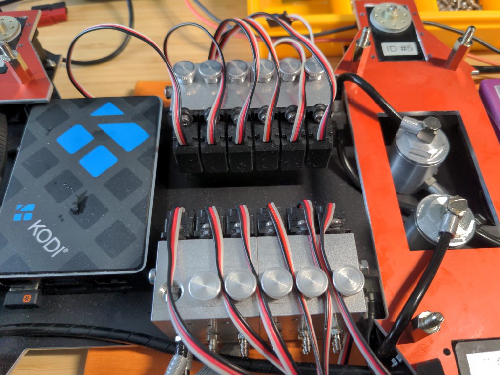
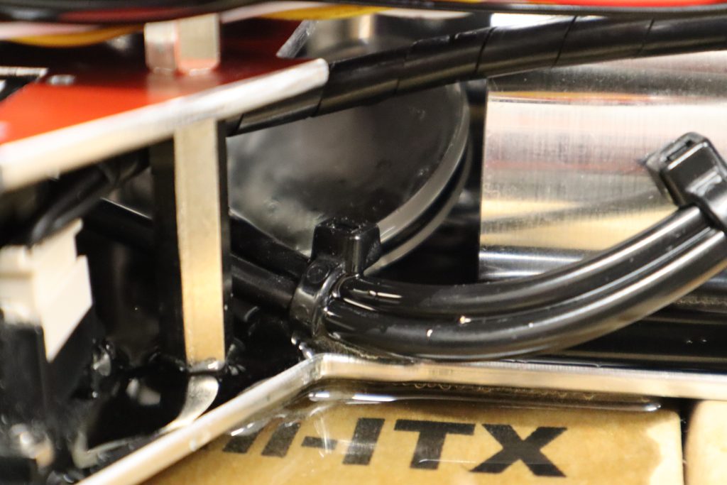
Finally, here’s a close-up view of one of the two hydraulic valve blocks:
T – 40 days: Assembly of legs with custom milled shafts
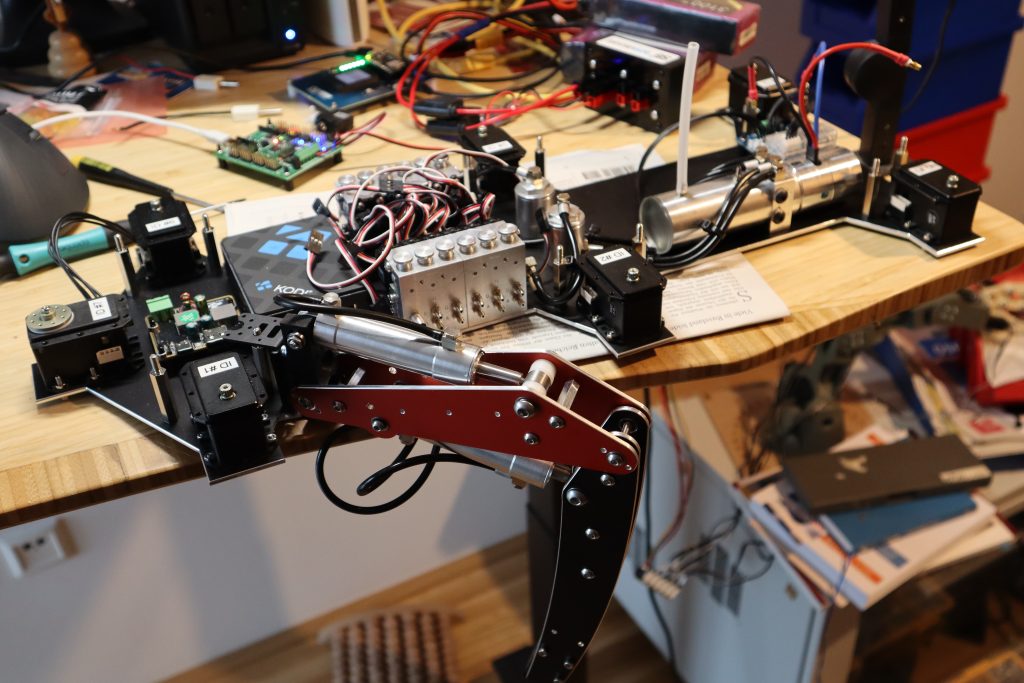
After the custom-made shafts arrived, it was time to assemble each of the robot’s legs. Robert Hahn, OE3BHC, kindly contributed his time and expertise in painstakingly manufacturing those shafts on a small lathe as a volunteer contribution. The image below depicts the first leg assembled with custom shafts rather than screws.
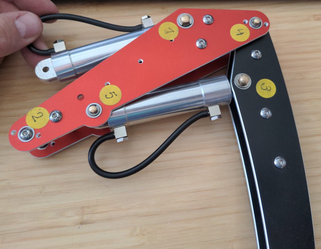
When you look at a fully assembled leg from the top, you can see how many small parts were needed to make sure the joints worked well:
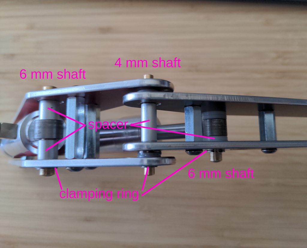
With all those shafts, spacers, and parts arriving, I spent an afternoon assembling all of the other legs.
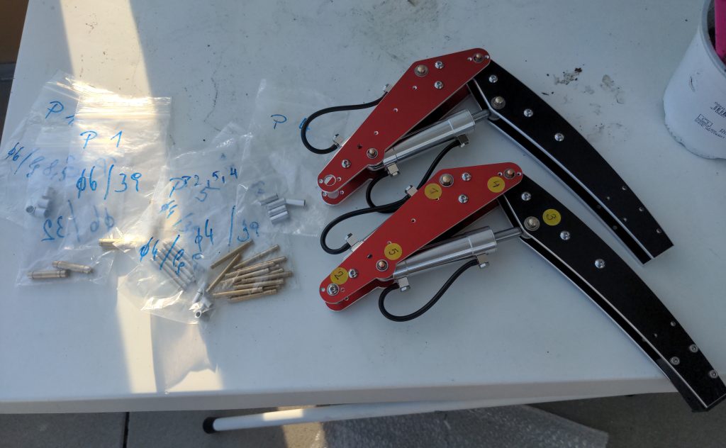
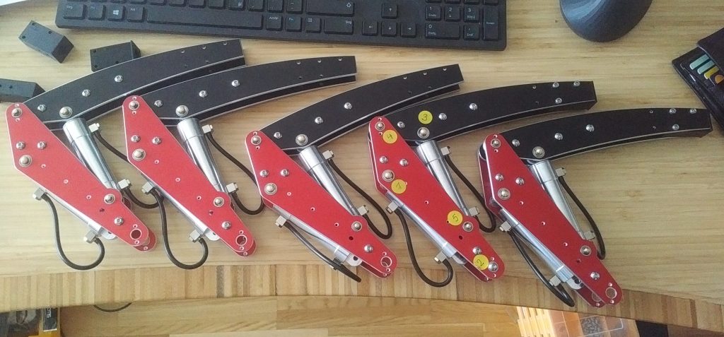
Only five legs could be assembled on this day because one leg was away for prototyping the custom leg controller board (more on that later):
At the tip of the tibia, 3D-printed (black) elements representing the hexapod’s leg’s actual „foot“ were inserted. These feet have a round hole in the middle that allows for the later insertion of a rugged contact switch that allows the robot to determine whether or not it has placed the foot on the ground.
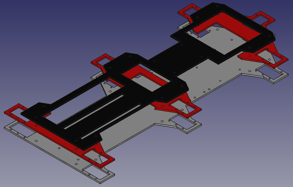
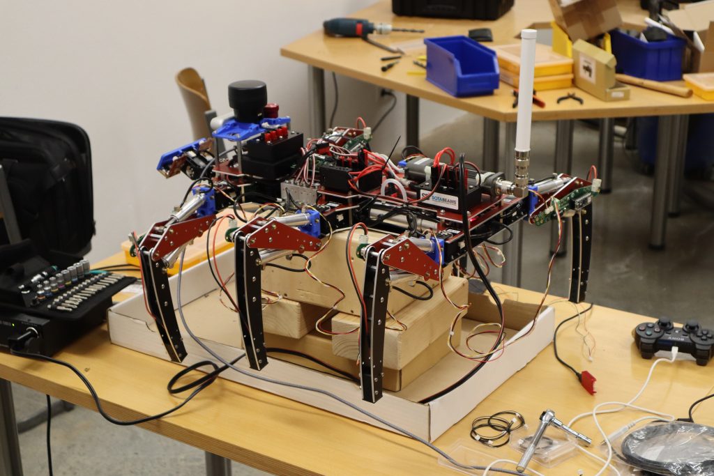
T – 38 days: Assembly of the top plates
It was now time to complete the mechanical assembly of the robot’s body. The parts were designed in FreeCAD immediately after receiving the base plate and confirming that it fit as intended. In total, four different plates were ordered. The first three plates (called middle plates) were designed to increase lateral robot stability by firmly enclosing the top and bottom of the Dynamixel MX-28AR hip servos.
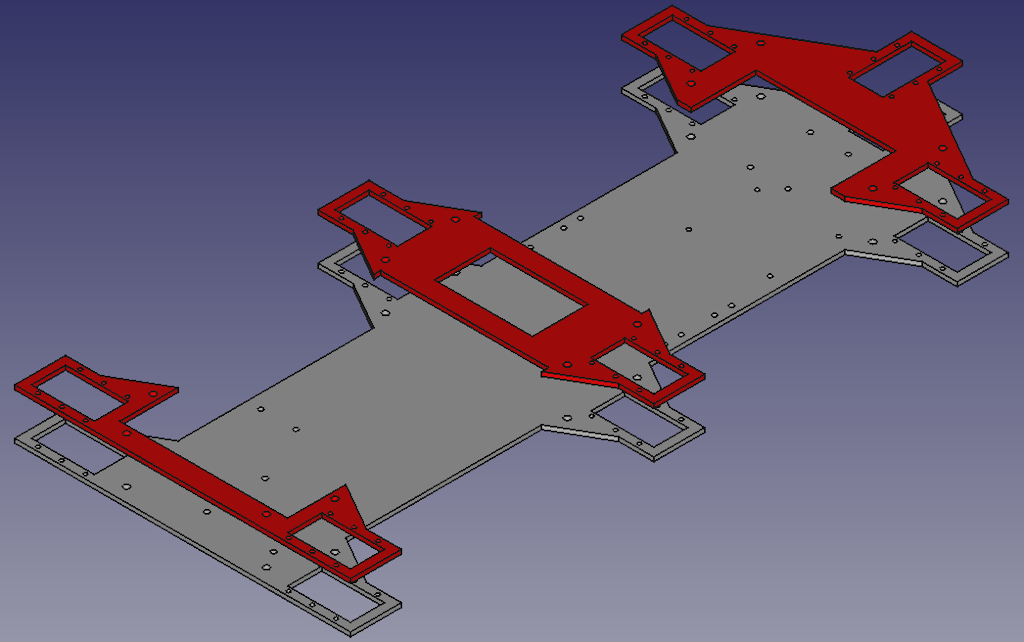
The final plate is mounted on top of the middle plates, increasing transversal stability along the robot’s mody. Also, cutouts in the right places let you get to the robot’s guts even after it’s all put together, so you can fix it if you need to.
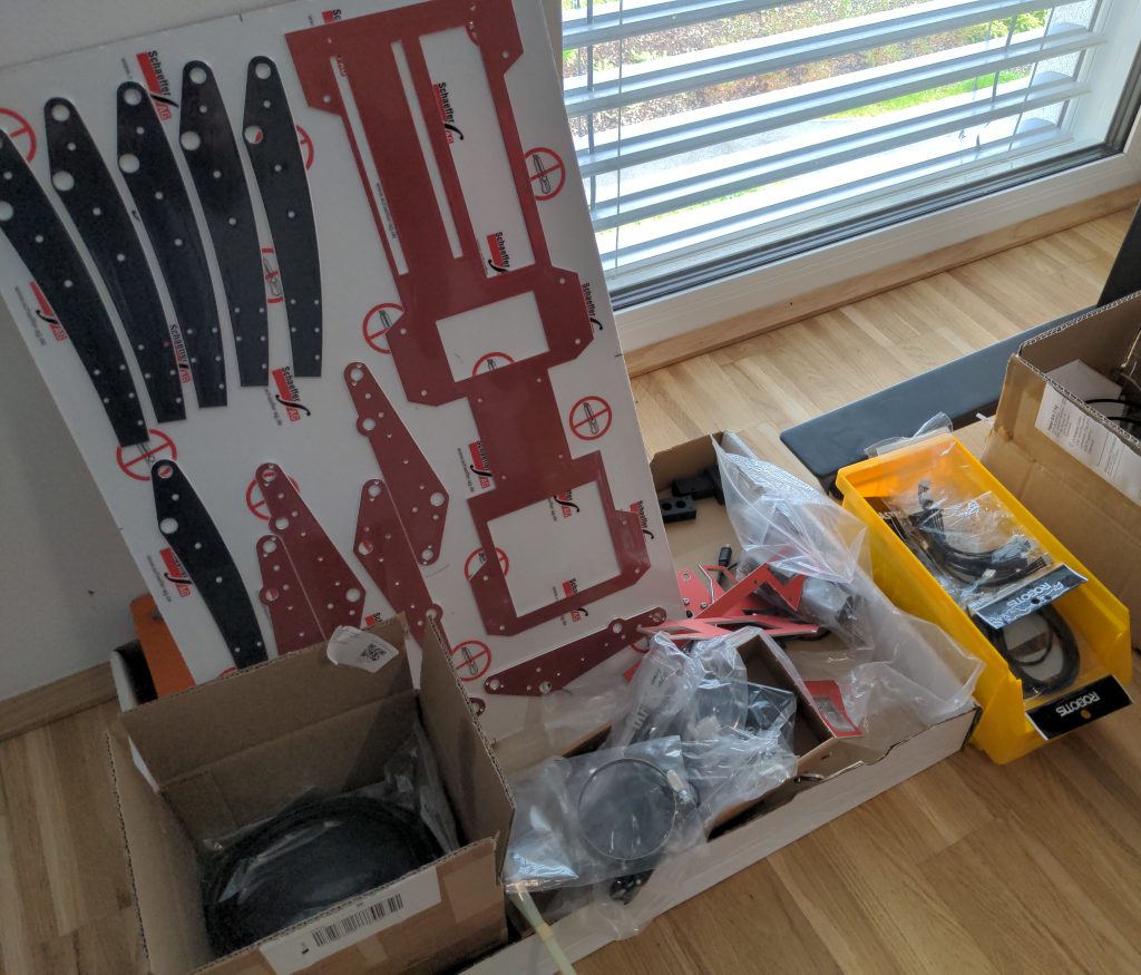
The image below depicts the shrink-wrapped, custom-milled parts delivered by Schaffer AG.
The middle plates must now be installed. They are securely attached to the base plate with threaded M4 distance bolts. As you can see, all of the Dynamixel servos are now mounted securely and ready to handle the huge force that the robot’s weight will put on them.
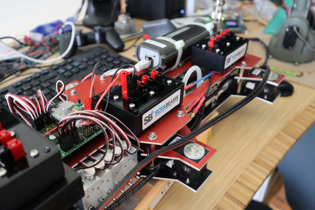
In preparation for mounting the L3X-Zs top plate, the servo cables of both hydraulic valve blocks are neatly arranged. This makes it easy to tell which cable goes to which servo, even when the servos themselves are hidden by the top plate.
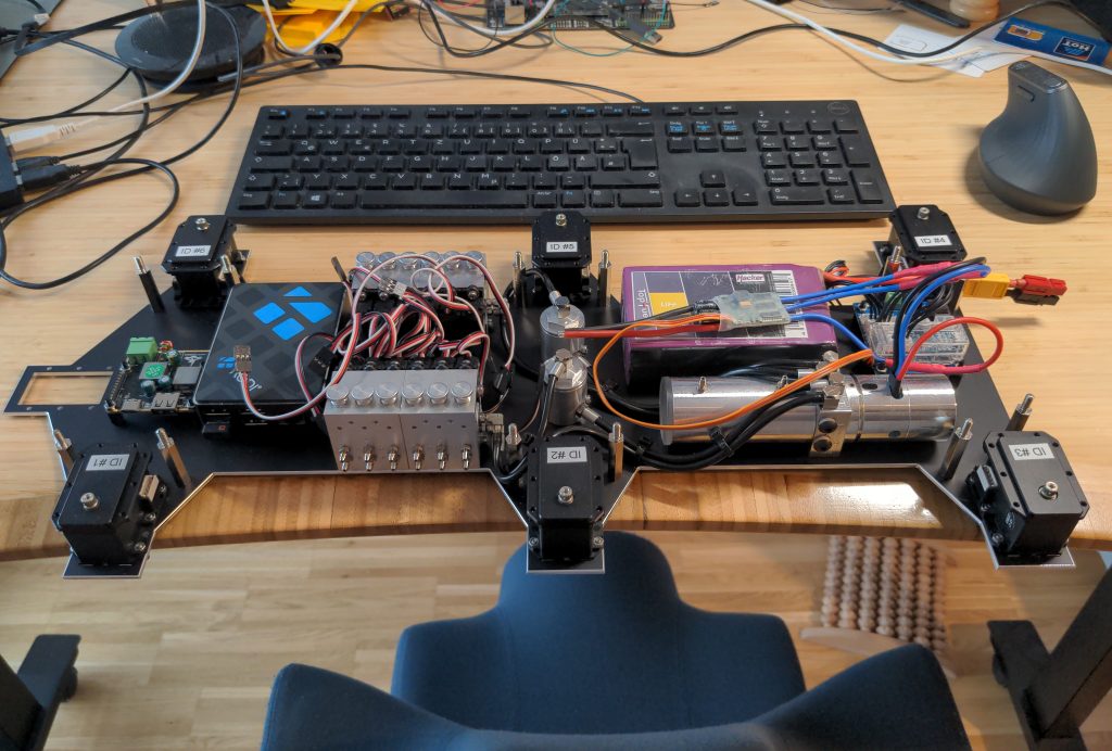
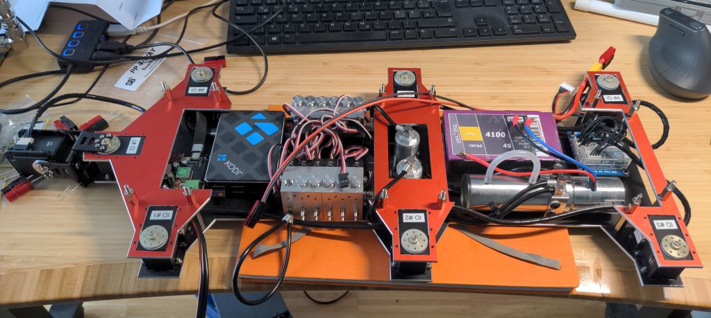
The mounting of the top plate is the final step in completing the robot’s body mechanical assembly. It is connected to the middle plates with threaded M4 spacers. Through carefully placed cutouts, you can see the Raspberry Pi 4 and its power supply, as well as the oil filters and hydraulic pump. You’ll notice that the hydraulic valve blocks‘ servos are no longer visible.
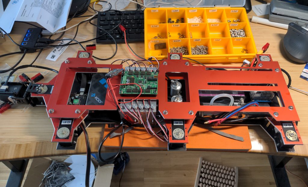
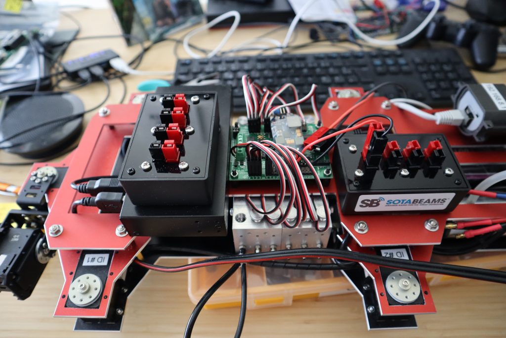
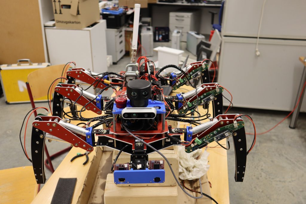
A Lynxmotion SSC-32U USB servo controller is mounted between the cut-outs for the Raspberry Pi 4 and the oil filters, and all servo cables are connected to its pins. It’s time for a general photo shoot:
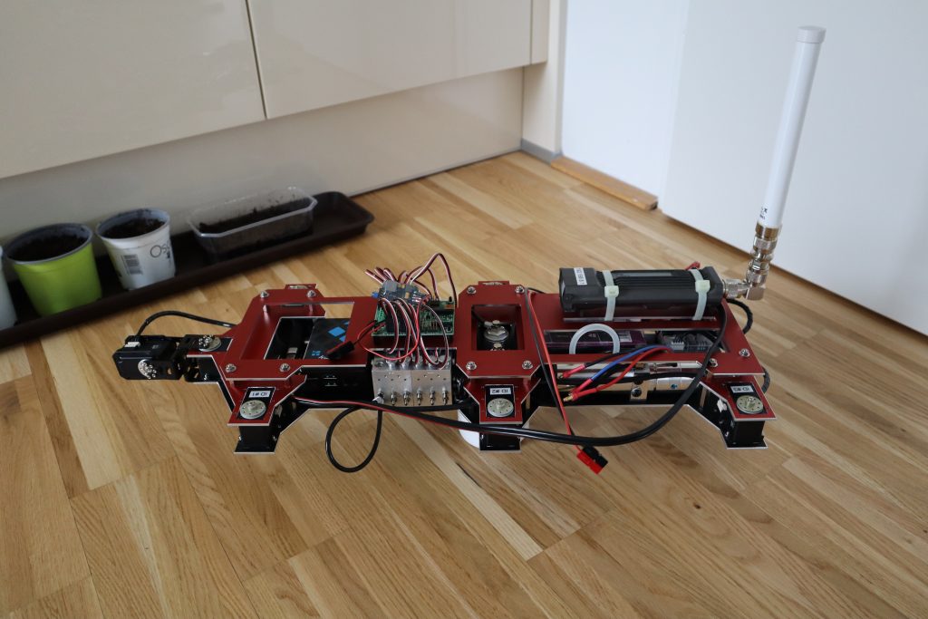
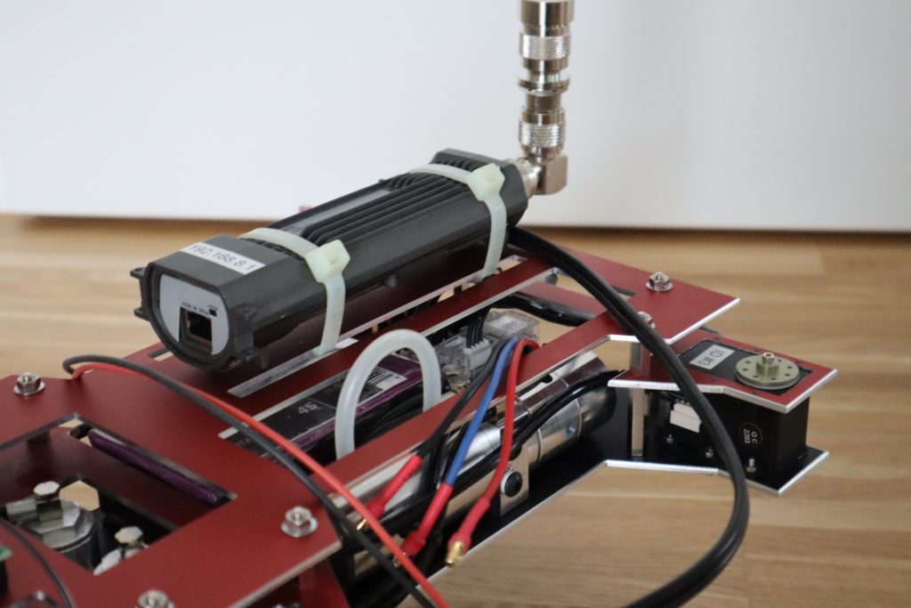
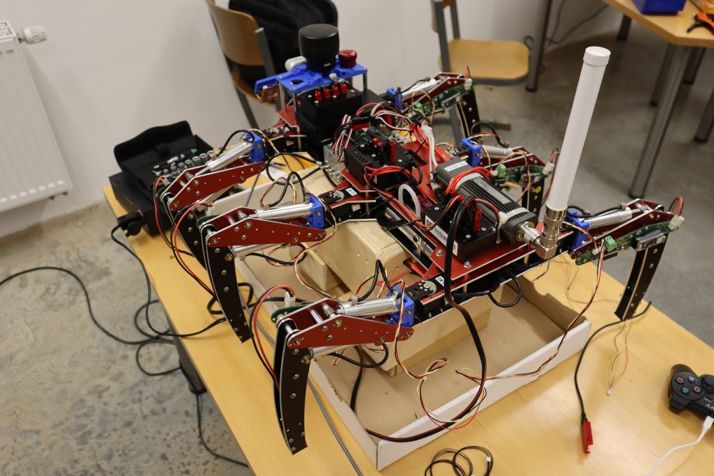
A MikroTik RBMetal5SHPn has been mounted to the back/right side of the robot for reliable wireless communication even in RF-challenged conditions. MikroTik routers are popular in the amateur radio community because they provide more transmit power than standard WiFi routers and are used to power the HAMNET.
The day’s final image is a close-up of the Lynxmotion SSC-32U servo controller. The top-mounted shrink-wrapped PCBs are RC-model battery eliminator circuits (BECs), which convert the main battery’s high voltage to a suitable 5V for servo control.
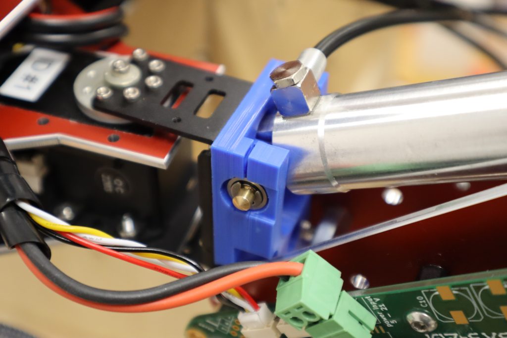
T – 14 days: Mounting of diametrically magnetised magnets for axis position sensing
Because the hexapods‘ femur and tibia joints are powered by hydraulic cylinders, additional circuitry is required to obtain the current angle of any given leg joint. This is accomplished by glueing diametrically magnetised neodymium ring magnets to the shafts that serve as the rotational axes for the femur and tibia whose magnetic field is picked up by digital rotary encoders.
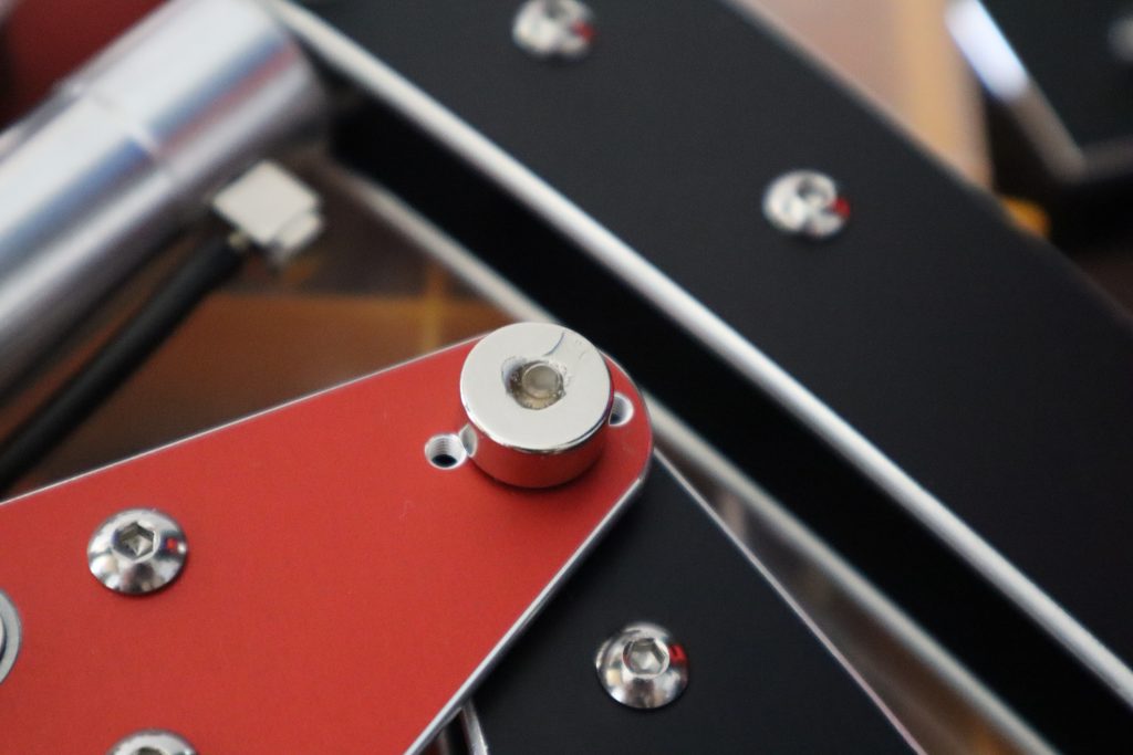
A diametrically magnetised magnet is one with the magnetisation direction running through its diameter. As a result, its north pole and south pole are on opposite sides of the curved surface.

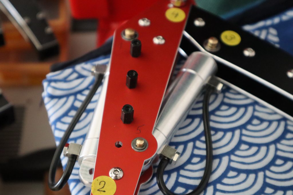
In preparation for the mounting of a custom developed PCB with ICs for rotational angle sensing, isolated plastic distance spacers with an M3 thread were mounted on one plate per femur.
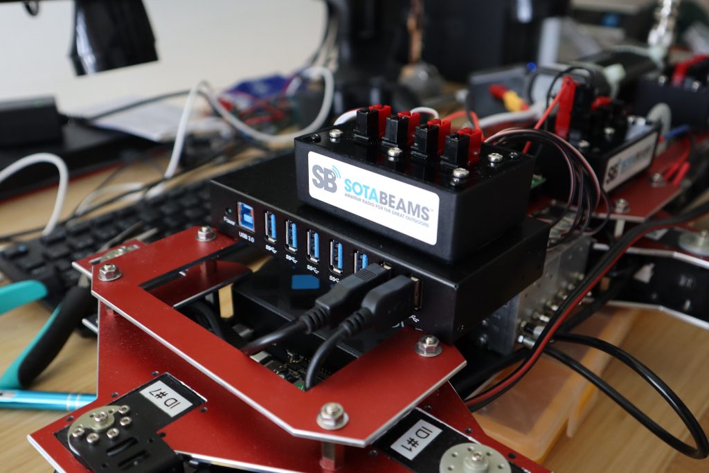
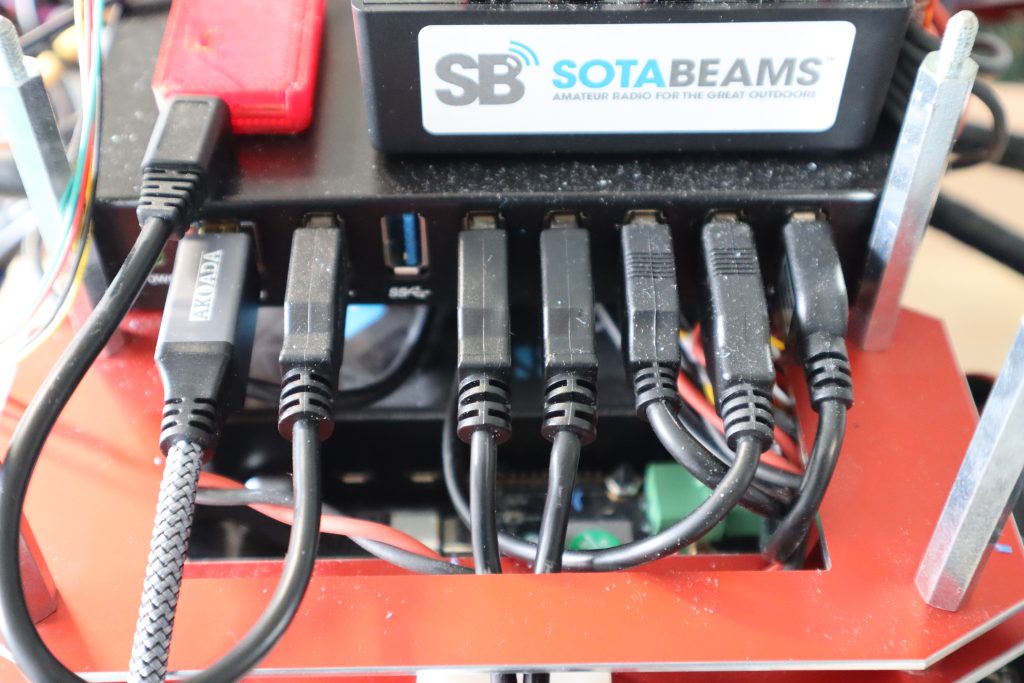
Because the L3X-Z contains a large number of USB devices (a fact that will be addressed in the upcoming redesign, USB is simply not an industrial grade field bus), an industrial (at least some concession) USB hub is mounted to the front of the robot. A 4-way power distribution block comprised of four interconnected Anderson PowerPole connectors is mounted on top of the USB hub to distribute the main battery’s energy to the numerous energy sinks.
On the middle plate is another power distribution block.
The robot’s rear is equipped with a final power distribution block. They work together to provide the necessary energy to their customers as needed.
T – 7 days: Final assembly
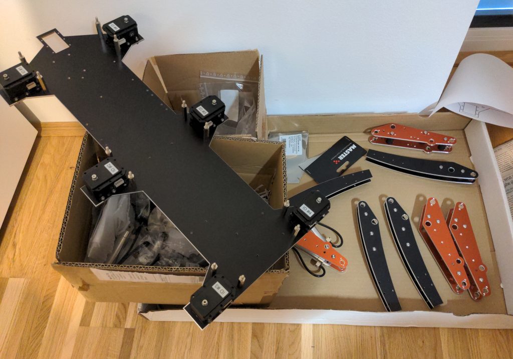
Despite the fact that the robot had improved by leaps and bounds, the fact remained that there were only 7 days left in the competition and the legs had yet to be mounted. As a result, I packed my car and drove to Deggendorf for a joint afternoon/evening of final robot assembly. I had no idea that I would not be leaving the JECC robots club premises until five o’clock the next morning.
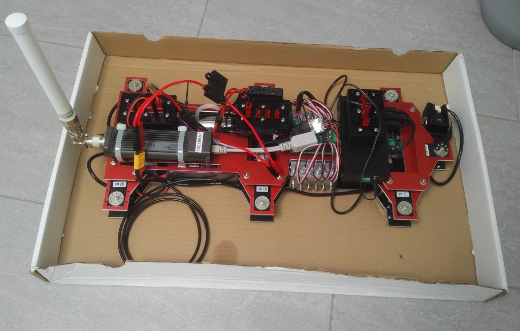
The main body of the L3X-Z was placed in a cardboard box and – due to space constraints – transported on the backseat of my car.
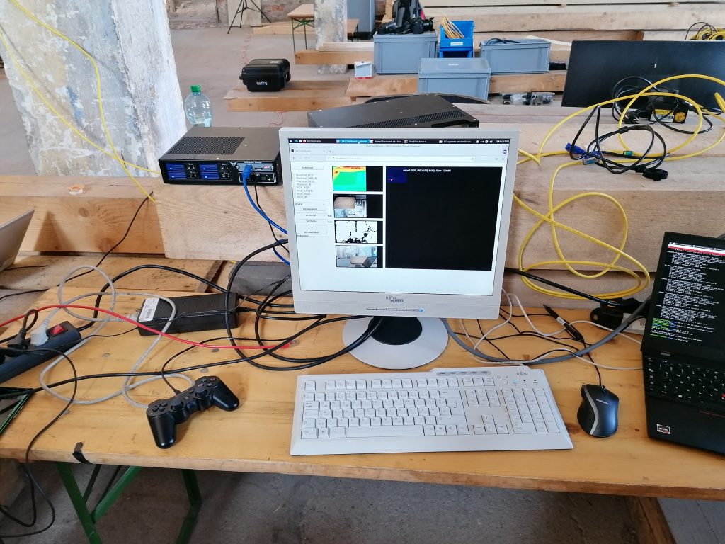
Upon arrival at JECC Deggendorf and lugging up all the parts to their first floors laboratory it was time to set-up the development station.
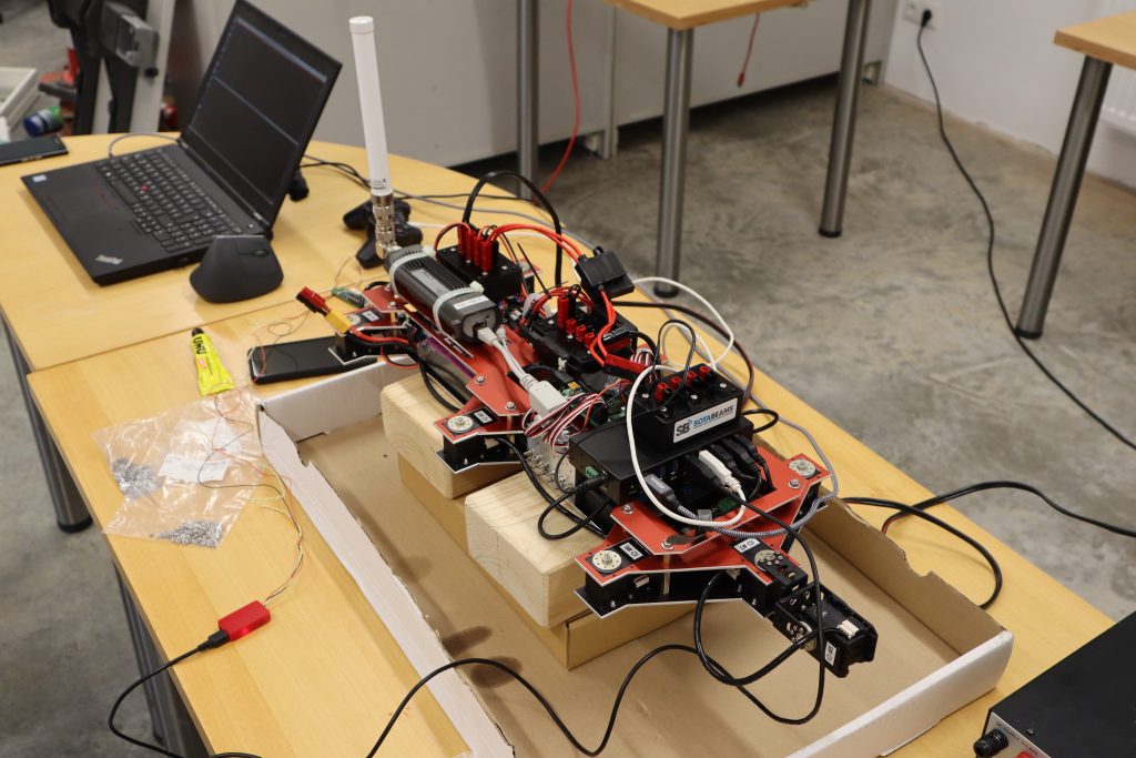
While still using the cardboard transport box, L3X-Z was propped up on some wooden blocks. While it was an unintentional decision at the time, it proved extremely useful when we were losing gallons of oil during the hydraulic assembly process. The paper box was crucial in preventing the spread of the leaking hydraulic oil throughout the laboratory.
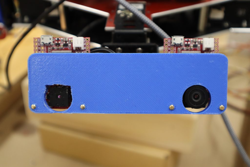
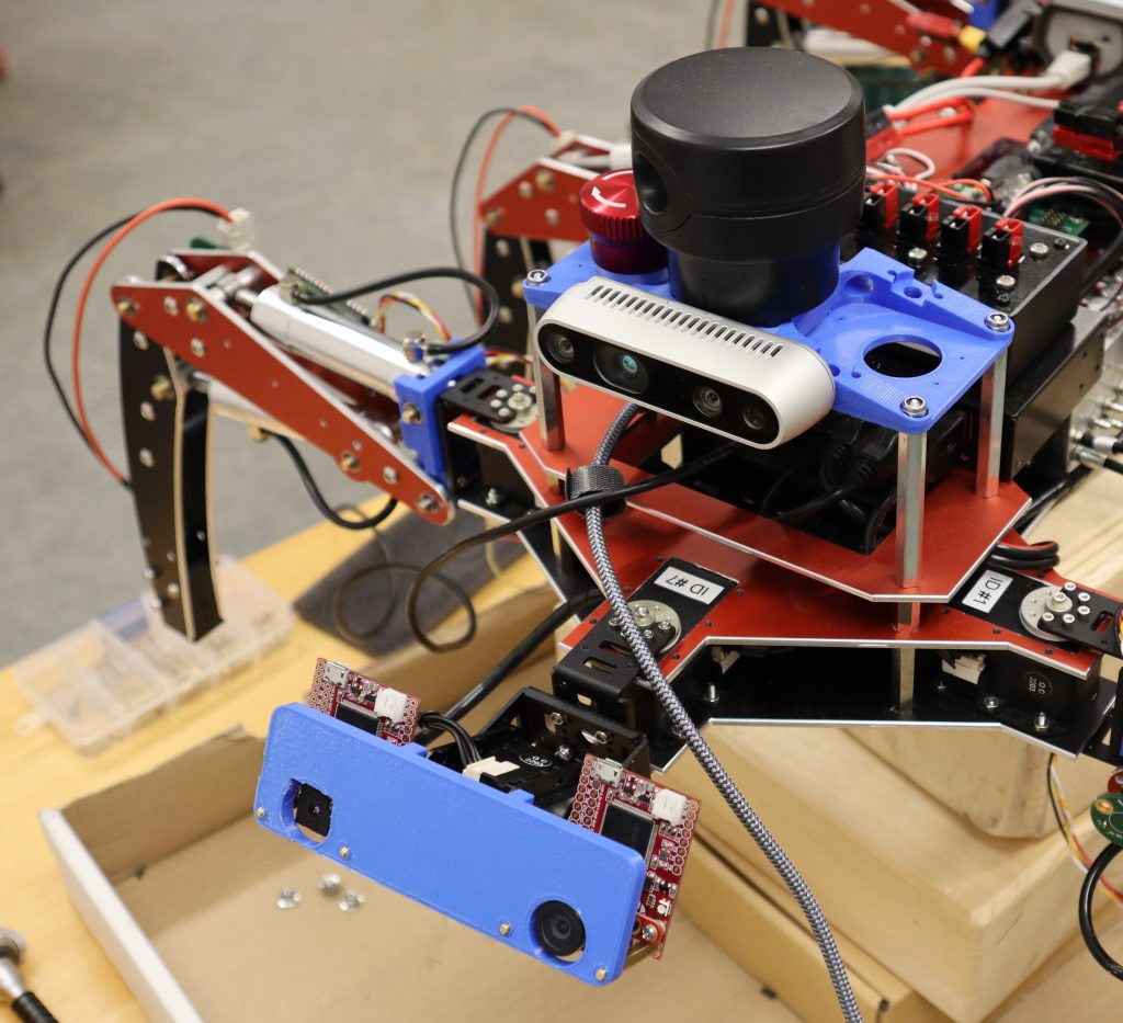
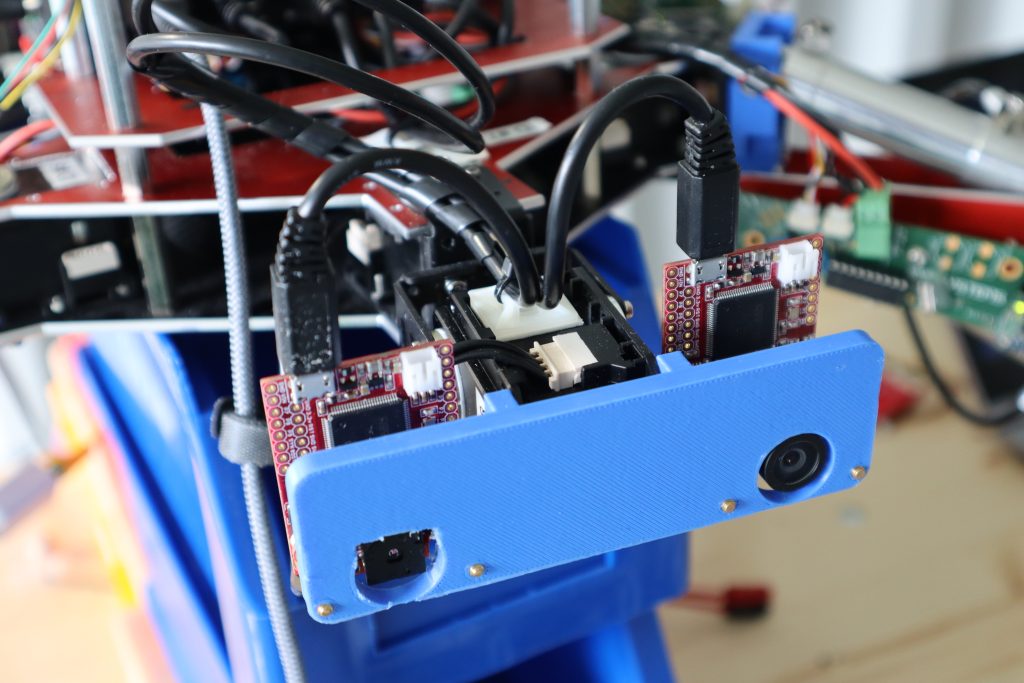
Up next was the assembly of the robot’s camera pan/tilt head. For sensing, the L3X-Z employs two OpenMV cameras. A colour view is provided by an OpenMV Cam H7 R2, while a thermal view of the robot’s surroundings is provided by a second camera in conjunction with the FLIR Lepton Adapter module and a FLIR Lepton module.
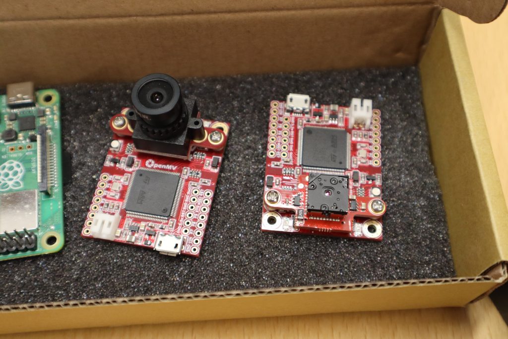
Jonas Wühr created a ROS driver for the OpenMV cameras in order to make the images captured by those cameras available within the ROS software framework.
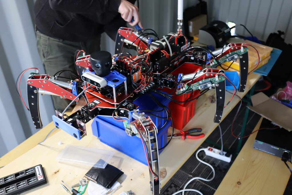
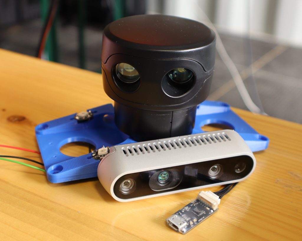
A multi-sensor platform consisting of an Intel® RealSense™ Depth Camera D435 and a Scanse Sweep 360° LIDAR was installed at the front of the robot (which was once purchased from a successful Kickstarter campain but has unfortunately ceased production since). A ROS driver for the Scanse Sweep 360° LIDAR was developed and can be found here. In addition, an emergency stop, as required by ELROB rules, has been installed on the sensor platform.
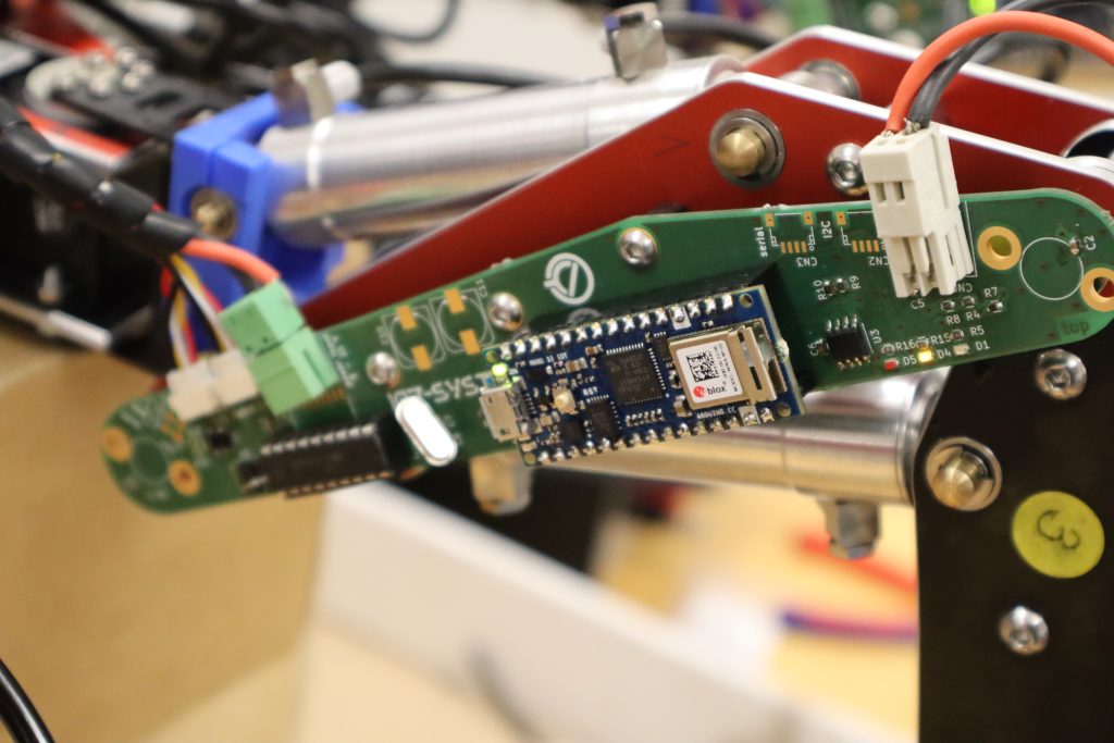
The leg controller PCB was then fitted to the femur of each leg. The PCB is mostly composed of two AS5048A (Arduino Library) 12-bit contactless rotational position sensors, which are used to sense the current position of the femur and tibia rotational axes via the previously mounted diametrically magnetised neodymium ring magnets. There is also the option of connecting a bumper sensor to determine whether a leg has made contact with the ground (or not). Finally, the board can determine the current battery voltage.
The leg controllers processing unit is an Arduino Nano 33 IoT board with an Atmel SAMD21G18 Cortex-M0+ microcontroller that, in tandem with a tried-and-trusted MCP2515 CAN Transceiver (Arduino library). It’s main purpose is to report the current angle of both femur and tibia rotational axis, the state of the bumper sensor as well as battery voltage to the central computer via an OpenCyphal/CAN interface. The firmware for the board can be found here.
The leg controller can be powered by connecting a USB cable to the Arduino Nano 33 IoT (which is also the default way of programming it), via a dedicated power connector, or via the CANVCC wire of the CAN bus. It would have been preferable for simplicity reasons to simply power the board via CAN bus, as this significantly reduces the required cabling overhead. Unfortunately, the Zubax Babel used as a USB-CAN converter can only source 100 mA, which was a bit less than the total of all 6 leg controllers required. As a result, we had to power them directly from the battery’s main power, which added 6 more twin-wires to the robot’s already fairly extensive wiring harness.
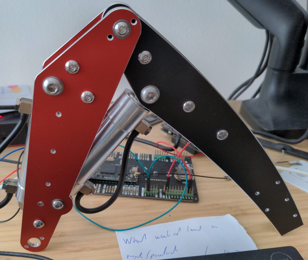
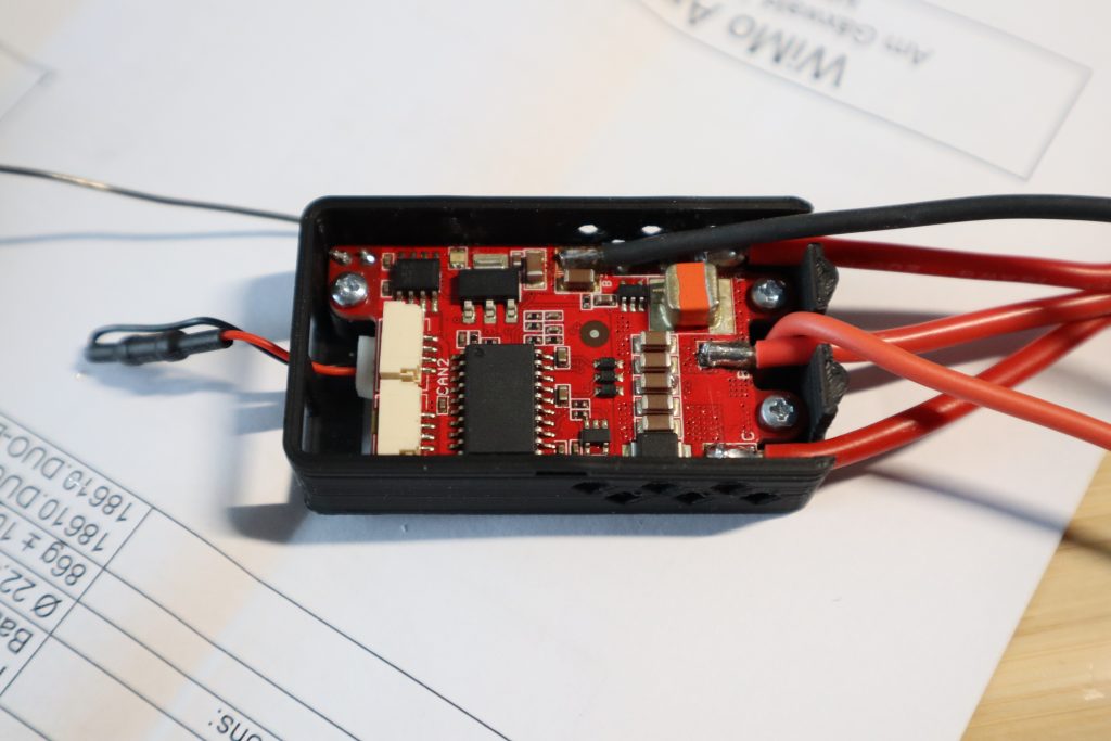
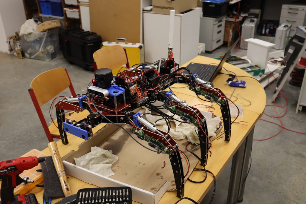
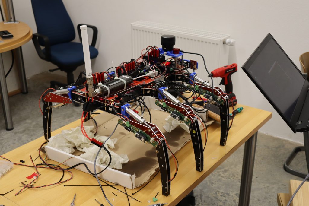
By this point, we had installed the leg controller PCB’s on each of the six legs and established a temporary CAN network (visible as free-flying wires on the image below). The Zubax Babel, with its 3D printed red enclosure, can also be seen lying on the desk and connecting via free-flying cables to the temporary CAN network.
With positional sensing online we were able to run a first test in order to extend a retract one of those six legs. Success!
After overcoming those first challenges, we proceeded by connecting all remaining cylinders to front-mounted hydraulic valve blocks. The numerous oily paper tissues clustered around the robot indicate that this was a very messy job.
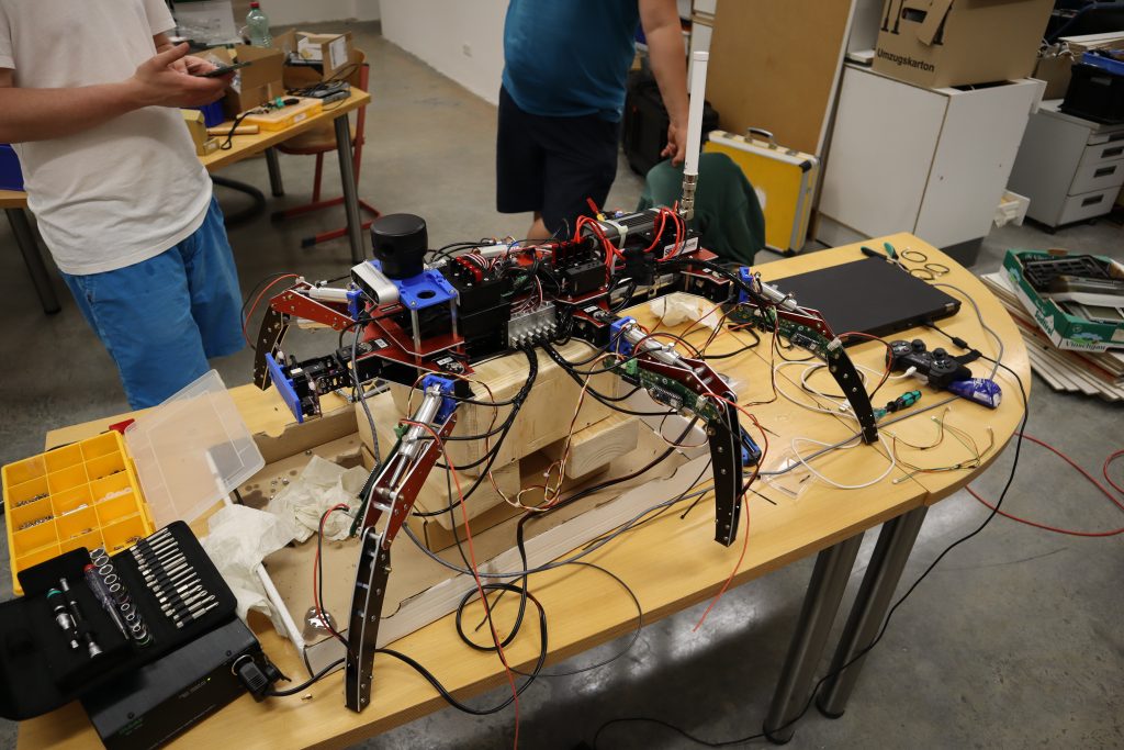
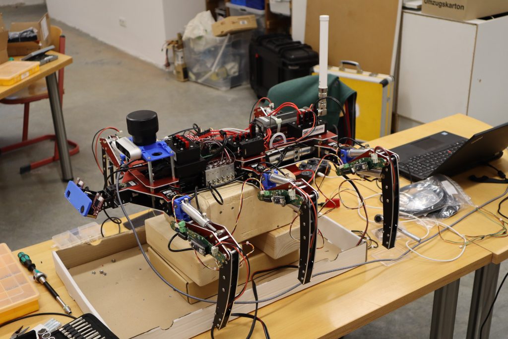
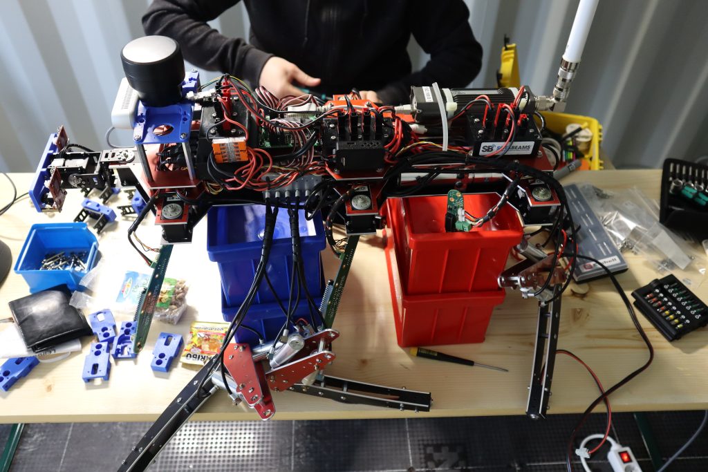
As more subsystems are brought online, the wire birds nest on top of the robot grows larger and larger.
Finally, we had successfully connected all of the cylinders to all of the valve blocks, and we were ready to test simultaneous movement of all legs.
We eagerly instructed the software to fully extend all legs. And all of the legs began to move! Unfortunately, we had reached a fairly late hour and were possibly no longer in full command of all our technical faculties. As a result, we forgot to remove the silicon tube connecting the hydraulic pump’s tank’s two pressure outlets. As a result of the pressure buildup within the tank, the transparent lid of the hydraulic pump was blown right off, resulting in a shot-like crack. This was followed by the expulsion of copious amounts of hydraulic oil into the robot’s difficult-to-reach interior.
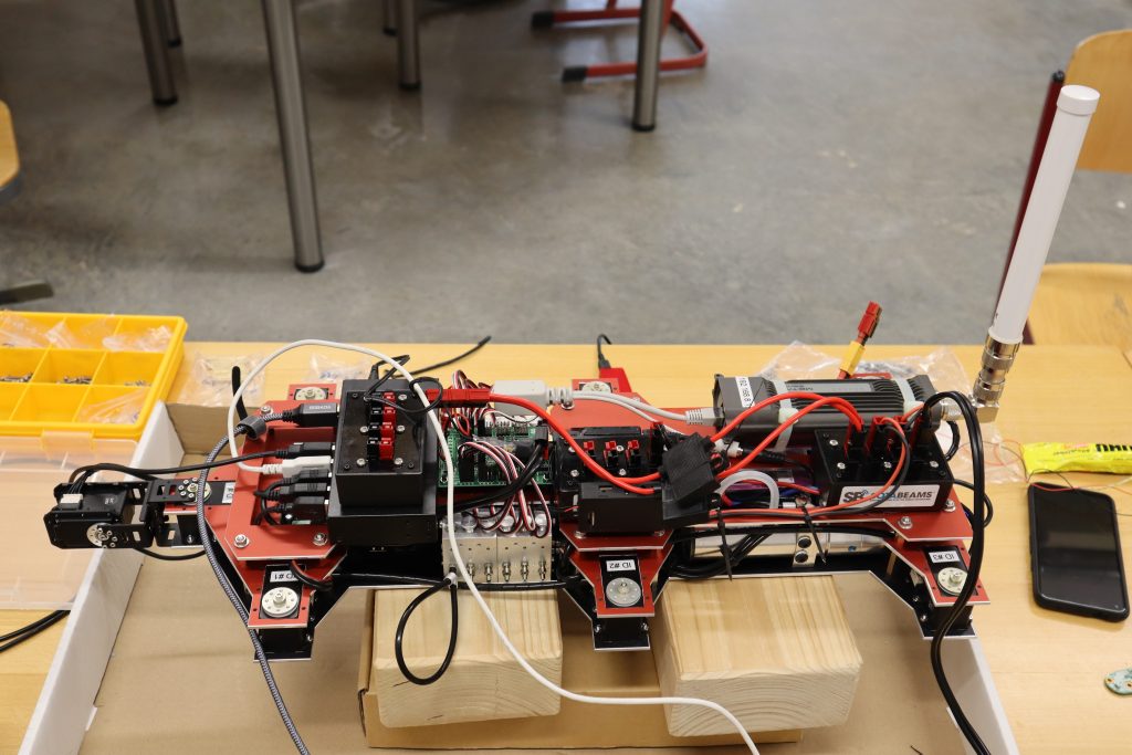
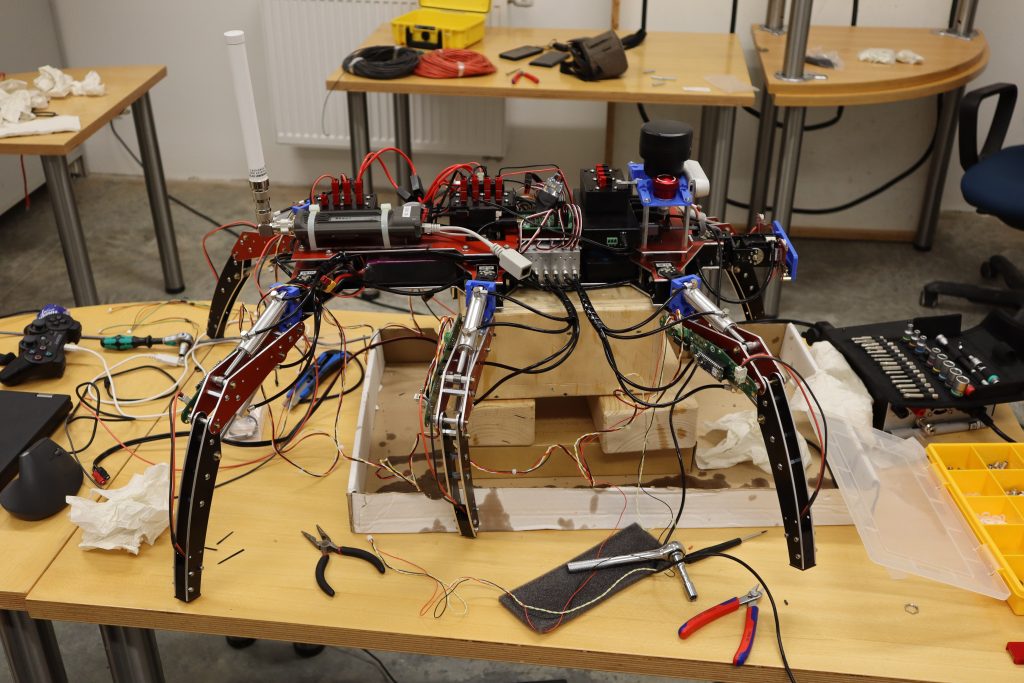
After the lid was replaced, the spilled hydraulic fluid was collected as thoroughly as possible, and the tank was refilled, it was time for more tests. L3X-Z with all legs fully retracted is shown below:
Following full retraction, which is required to obtain a „zero reading“ on the rotational sensors, the legs are fully extended into the hexapod robot’s preset standing position.
We were fully extending our legs when we heard six sudden cracks, which is never a good sound to hear. Upon investigating the source of the sound, we discovered that there was still a minor design flaw within 3D-printed hip joint connectors, which resulted in the hip joint breaking apart along its printed layers upon full extension. This was caused by pressure from the back of the cylinder against the metallic servo bracket.
It was now four o’clock in the morning. As a final step, we arranged the free-flying wire network so that no connectors could be accidentally torn off when carrying the large and bulky robot.
We were witnessing the dawn of light when we finally left the garage at 5 a.m. Despite being exhausted, we had manged to make a big push forward with less than six days until the event.
T – 2 days: Packing for ELROB 2022
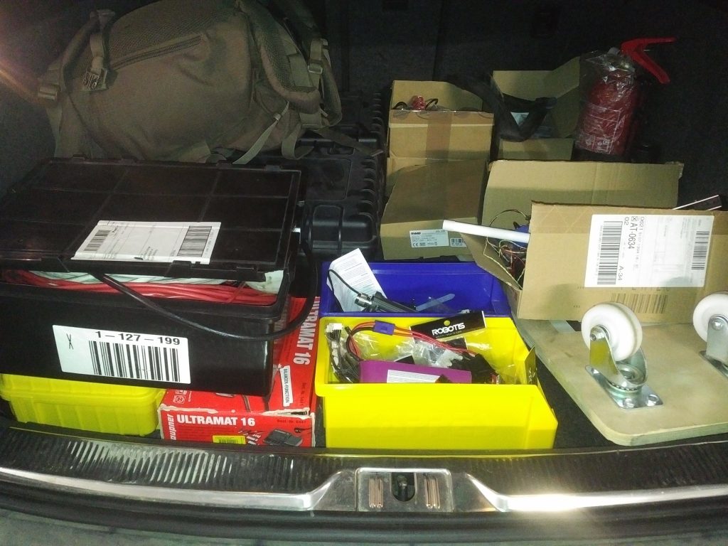
I began packing all tools, spare parts, power supplies, and measurement devices I could think of about two days before our departure to ELROB and piled everything into several multi-purpose water-proof suitcases.
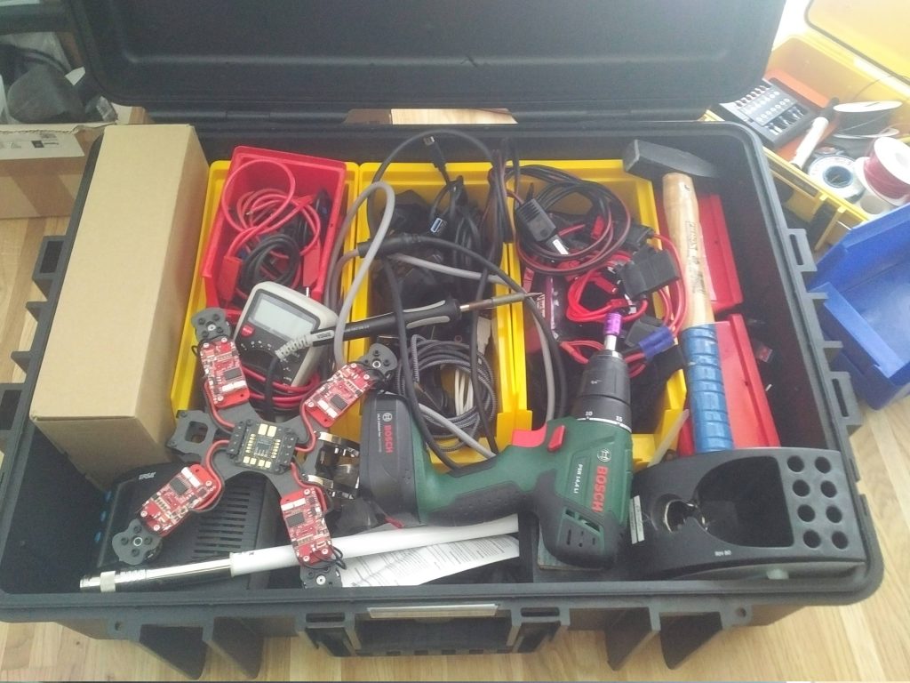
It was then time to load the car. L3X-Z took up residence in the car’s trunk, perched on top of one of the tool/parts/etc. suitcases. Because the robot was so large, there was no other space available in the car to hold it.
T – 1 day: Completing the robot on-site
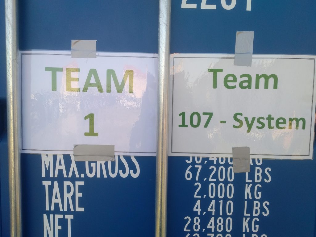
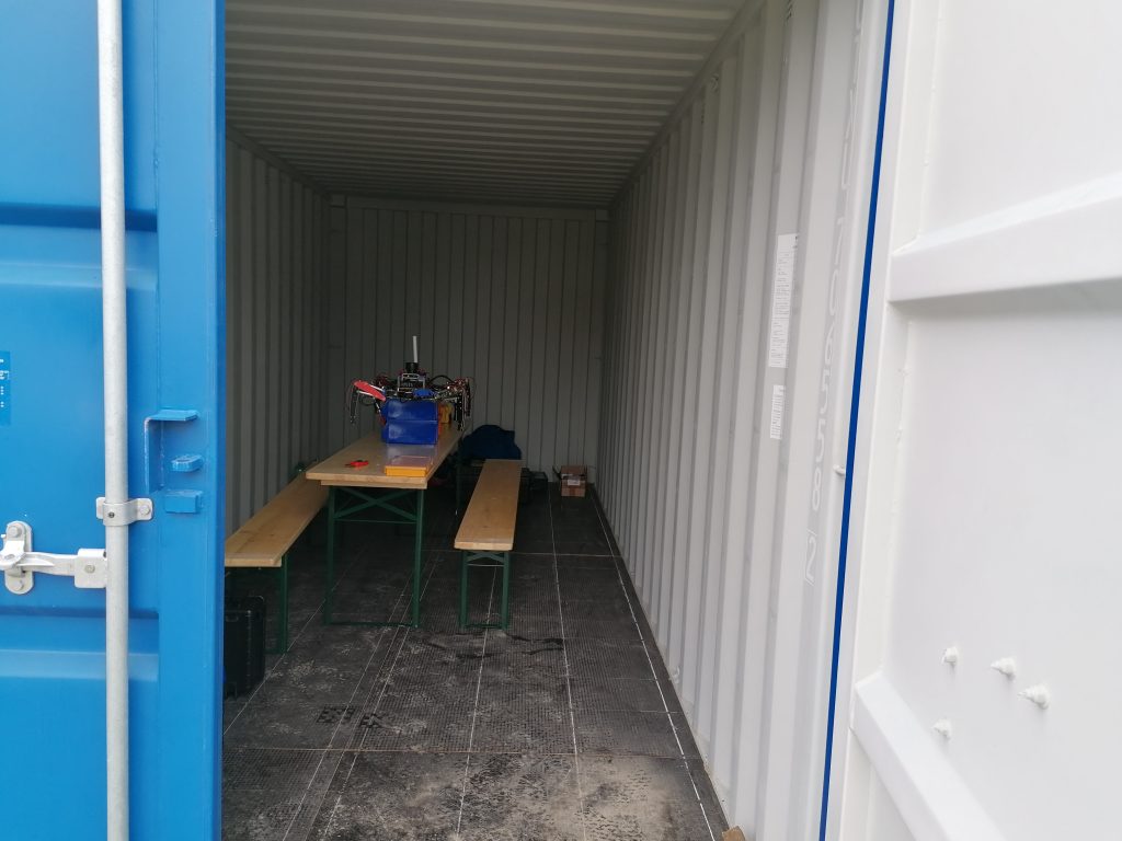
We started organising ourselves and our gear as soon as we arrived. For the duration of the event, we were assigned a standard shipping container to store the robot and perform assembly and development.
The container included two benches, one table, a construction-style lamp, and a power distributor (which on the day of arrival had not yet been connected to power).
The first order of business was to remove all legs and replace the broken 3D-printed hip joints with newly manufactured parts.
The legs were then remounted using the most recent 3D printed hip joint connector, which did not suffer from the severe issue of breaking upon full extension.
We were able to complete a full calibration sequence at the end of the day, which consisted of pulling all legs up to their highest position with all cylinders fully retracted. At that point, the magnetic sensor reading is captured and will be used as an offset to calculate the correct angle of the femur and tibia rotational axes.
We left the compound because the power from our notebooks was running out (and there was no external power available).
T – 0 days: Completing the robot on-site and official start of ELROB
Today marked the official start of ELROB, which included welcome speeches and a summary of the event. Unfortunately, L3X-Z was still far from completed, so we set out to wrap up the remaining tasks as soon as possible. As a first step, I connected the colour and thermal vision OpenMV cameras to the Raspberry Pi 4 single board computer.
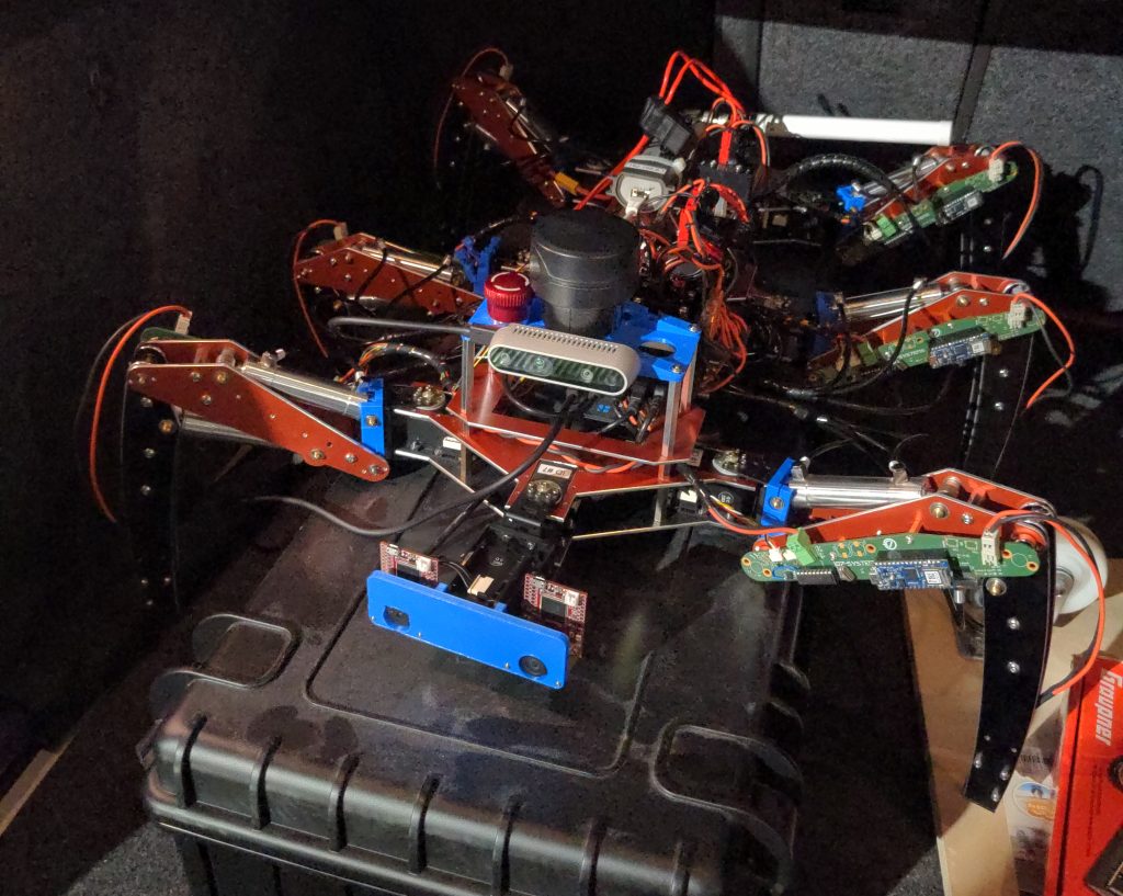
With the majority of the USB slave devices – and there were far too many – connected, the USB-Hub became quite crowded. The red enclosure in the upper right corner of the image houses a Zubax Babel USB-to-CAN converter, and the black box next to it houses one of the power distributors.
The ELROB rules required a tri-color status light to broadcast the robot’s system status to bystanders. To accomplish this, four NeoPixel RGB LEDs were mounted on the sensor platform and controlled by an OpenCyphal-enabled device called auxiliary controller (firmware).
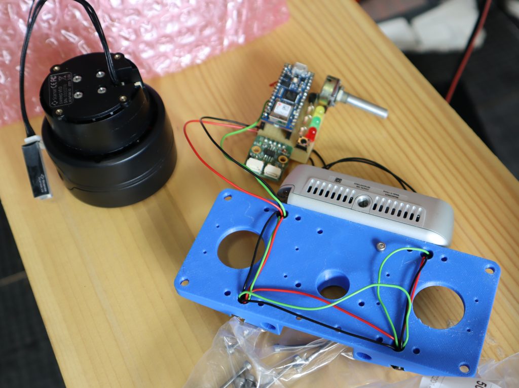
After the RGB LEDs were installed and tested, the Scanse Sweep 2D 360° LIDAR was reinstalled. The small PCB in front of the RealSense depth camera is a TTL-to-USB converter which helps connecting the scanner with the Raspberry Pi 4 SBC.
Meanwhile, Pavel Kirienko had established himself next to the robot and started working on the control code for a ripple gait. Ripple gait is a type of gait in which only two legs are lifted at any given time, with the remaining legs resting on the ground. It’s worth noting that the code base previously supported „only“ an abstract interface that allowed the user to set the desired target angle for each joint and control Dynamixel MX-28AR servos, hydraulic valves (via hydraulic servos), and the hydraulic pump to achieve the desired target angle. Only the groundwork for implementing a gait control had been laid, but no gait had yet been implemented.
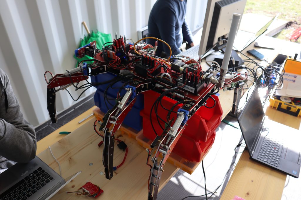
Throughout the day, Pavel worked on the gait and Jonas worked on the robot’s wifi interface and base station setup. Meanwhile, I was working on resolving numerous smallish issues, improving cabling, assisting with testing, and providing general feedback on the system design. Finally, we were ready to put the walking algorithm to the test:
It should be noted that the mistake from the late-night building session in Deggendorf was repeated, resulting in another blow-off of the hydraulic pump’s transparent lid due to our failure to remember that airflow into the hydraulic pump was required. Hydraulic oil was splattered everywhere, making our hands, tools, and keyboards increasingly sticky.
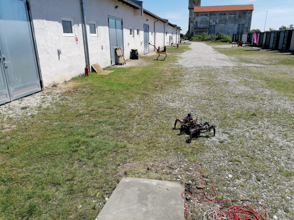
Finally, the software had advanced far enough that we could conduct our first walking tests outside of our shipping container. These tests continued throughout the day, and numerous minor and major issues were resolved.
We had planned to work late into the evening, but despite the organisers‘ announcements to the contrary, we had to leave by 20:00. This was reinforced by cutting off the powers, leaving us with no choice but to call it quits.
T + 1 day: Completing the robot on-site and competition day
D-Day. We were scheduled to do our graded run at 14:00. Unfortunately, there were still a few issues that needed to be resolved. One of these was the programming and mounting of the radiation sensor board, as our chosen scenario included live radioactive sources that the robot needed to detect and map. Due to time constraints, a spare leg controller board was used as a base to which a radiation sensor was attached. It sent radiation data to the main computer via OpenCyphal/CAN, which was then displayed on the robot’s front panel.
Throughout the day, we worked feverishly to improve the robot’s gait and overall software and hardware stability. We were especially affected by power surges, which resulted in the loss of all USB slave devices, which could not be recovered even after a system reboot. The only viable solution was to power cycle the entire system.
We kept trying different approaches to stabilise the system’s power supply because we suspected ground shifts to be the main cause of the difficult-to-manage USB outages.
When our time was up, we went to the preparation checkpoint to wait for our turn to set up the robot.
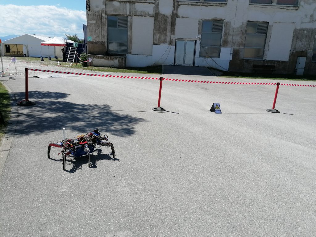
After being led inside, we immediately started setting up, booting up the control stations, and turning on all systems. When everything was ready, we checked in with the officials and launched L3X-Z. The robot took a few steps over the starting line… until it was killed by another power surge. We were allowed to revive it because its back legs were still behind the starting line – once your robot has completely left the starting line behind, you are no longer allowed to touch it.
In a desperate attempt, we removed all fuses, effectively connecting all robot-mounted batteries in parallel. We hoped that by removing the fuses, we could reduce the total resistance of the power-path, thereby avoiding the dreaded ground loops. We restarted after those changes, and the L3X-Z raced past the starting line once more. The emergency measures appeared to be effective!
Unfortunately, our good fortune did not last. A few metres into the scenario, the robot experienced another power surge, effectively shutting it down. We attempted to restart it remotely (because physically touching it was no longer permitted), but the USB slave devices did not turn back on. This prevented us from communicating with all of the OpenCyphal/CAN-connected control devices, thus preventing further robot locomotion. We finally had to call it quits after exhausting every possible option.
Despite this significant setback, I am optimistic about the entire experience. We set out to create a legged walking robot platform in only 80 days and succeeded in getting something so intrinsically complex moving. Many flaws were discovered, which will be addressed in the weeks and months following this event so that we can return stronger next year!
Alexander Entinger is a highly experienced embedded engineer with a focus on robotic systems. By providing hard-won expertise designing embedded systems for real-world embedded applications Alexander Entinger is helping companies developing robotic systems or components for robotic systems to achieve their desired business outcomes.